Closed Crankcase Ventilation: What is it and what purpose does it serve?
Text and photos by Steve D’Antonio
Copyright December 2013
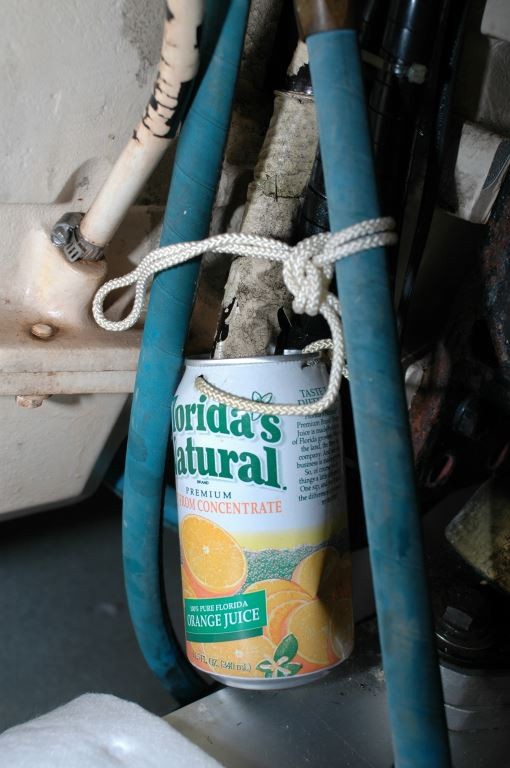
Fifteen or more years ago this is what commonly passed for a crankcase ventilation “system”. The orange juice can is actually an option, it’s been added by the vessel’s owner to catch condensing oil vapor that exits from this hose. Most units were simply a hose that was routed from the valve cover and down the side of the engine, which under normal circumstances emitted water and oil vapor and the occasional drop of oil.
When I was teenage kid helping a neighbor work on his boat, a stern-drive-equipped runabout, I recall my first encounter with the engine’s crankcase ventilation system. This boat had seen a hard life and the engine, before its eventual rebuild, was tired to be sure. A pair of hoses routed from the top of the valve covers on this eight cylinder engine to the carburetor air intake emitted a constant stream of “steam” and emulsified oil froth, which ultimately fouled the carburetor and intake manifold. I eventually learned this was a sure sign that the piston rings were worn and the engine was in need of a rebuild.
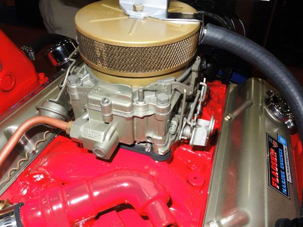
A traditional crankcase ventilation system used on a gasoline V-8 engine. Hoses from each valve cover direct crankcase gasses into the flame arrestor and from there into the carburetor. Baffles in the valve covers reduced, but didn’t eliminate, the flow of oil vapor that was ingested into the air intake.
Crankcase ventilation systems have taken many forms over the years on both automotive and marine engines. The term “crankcase ventilation” refers to the venting and removal of gasses created as a result of a natural process that occurs in almost all internal combustion engines, gas and diesel. The combustion chamber, a space located between the top of the piston, often referred to as the crown, and the stationary cylinder head, contains the intense pressure of combusting fuel, flame and soot as well as compressed air, fuel mist and exhaust gasses.

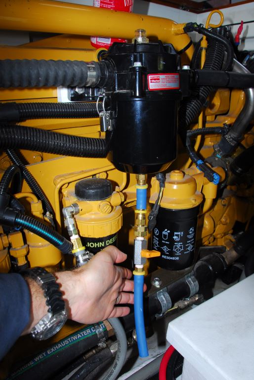
After market crankcase ventilation systems like the one shown here are now common, many are supplied as original equipment by engine manufacturers. The blue hose at the bottom drains coalesced oil back to the oil pan.
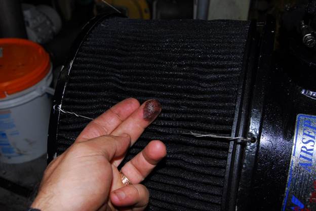
This air filter, part of an aftermarket crankcase ventilation system, is saturated with oil and long overdue for service, and the same is likely true of the engine it serves as well.
All or most of these components of the internal combustion process are contained within the combustion chamber by a seal created between the piston and the cylinder wall using a series of piston rings. It’s remarkable when one stops to think about this, but for a few microns worth of oil that remains on the cylinder walls the “seal” is achieved entirely with metal to metal contact, and that metal is moving at an incredible rate of speed, and continuously. But for the oil the friction would quickly melt and fuse the rings to the cylinder walls, and occasionally does in the event of a lubrication malfunction.
Rings are very hard, often chrome-plated steel or cast iron, spring like devices, they are C-shaped and the ends nearly touch when installed on a piston, and ultimately do touch when heated, which make up the difference in diameter between the inside of the cylinder and the outside of the piston. Rings maintain the vast majority of gasses, soot, fuel etc as they move along the cylinder wall at the blinding speed of between 20 and 40 feet per second under intense temperatures that may reach as high as 1000°F and pressure of over 600 psi.
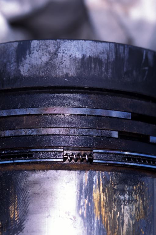
Worn out, broken or otherwise damaged piston rings can be the source of excessive crankcase pressure. In spite of the fact that they are metal, they achieve a remarkably good seal between the piston and cylinder wall. The upper two rings contain the cylinder’s compression, the lower rings, with the spring-like device, are designed to remove oil from the cylinder wall on the piston’s downward stroke.
Inevitably, even on an engine that is in good tune and one that is not suffering from extreme wear, some of the gasses that are contained within the combustion chamber leak or “blow” by the piston rings. These gasses, once they pass by the rings and into the crankcase (the “body” of the engine) are referred to as blow by. Collectively, blow by includes soot or particulate matter, water vapor, unburned fuel and exhaust byproducts such as carbon dioxide, carbon monoxide and nitrogen oxides to name a few.
Dealing with blow by, even the normal amount, has taken on several different forms over the years. In some cases and even recently it was simply vented to the atmosphere, known as open crankcase ventilation, which, on a boat means into the engine room. This type of crankcase ventilation hose usually snakes down the side of an engine to the bilge where it ideally emits just a small amount of gas, oil and water vapor.
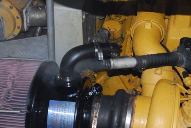
This crankcase ventilation system installation represents good intentions with poor execution. Oil vapor that is coalesced inside the black canister must be plumbed to drain back to the oil pan.
In most cases it’s directed from the crankcase via a hose or hoses to the air intake manifold, closed crankcase ventilation or CCV, where it’s ingested and “burned” by the engine in a recycling process of sorts, and then emitted with the exhaust.
The “Stanley Steamer” effect exhibited by this disconnected crankcase ventilation hose is a clear indication of excessive pressure.
It’s somewhat incongruous, however, in that engine air intakes are equipped with efficient and expensive air filters that are designed to keep contaminants out of the engine, while the crankcase ventilation system sends contaminants back into the engine. In general, however, for an engine whose rings are not worn, the level of contamination is relatively minor. Most crankcase ventilation systems include baffles through which the gasses and vapors must pass, capturing some of the oil vapor, returning it to the crankcase. These baffles are far from perfect, however, and depending upon the engine and conditions under which it’s operating oil vapor enters the engine and is burned. This creates excess soot and carbon accumulation in the combustion chamber as well as in the exhaust gasses that are left in the vessel’s wake.
As valuable as they are, after-market crankcase ventilation systems are only effective when properly installed. This one isn’t, its outboard end droops down, preventing oil from draining properly.
The quality and effectiveness of crankcase ventilation systems ranges from primitive, the hose leading into the bilge, to sophisticated, serviceable, monitorable baffled chambers. The goals of the latter closed system are multiple. One, to “recycle” gasses and unburned fuel, and two, to prevent these gasses from escaping into the atmosphere/engine room. In addition to making the engine room greasy or sooty, these byproducts are unfriendly to the environment.
Telltale signs of excess crankcase pressure are often visible if you know what to look for. In some cases, a seemingly simple oil leak is in fact the result of pressure pushing oil past seals or gaskets. Chronic crankcase or valve cover leaks in that reappear after they have been repaired are also a sign of potential excess pressure.
Three, to reclaim oil by turning oil vapor back into fluid and then diverting it back to the crankcase so it can go on to lubricate the engine once again, rather than being burned in the combustion process.
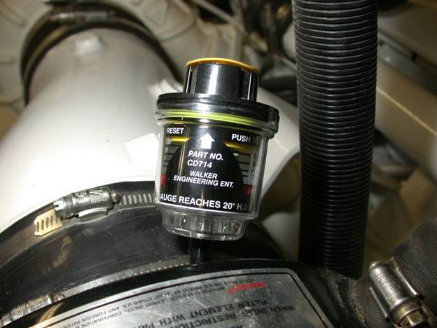
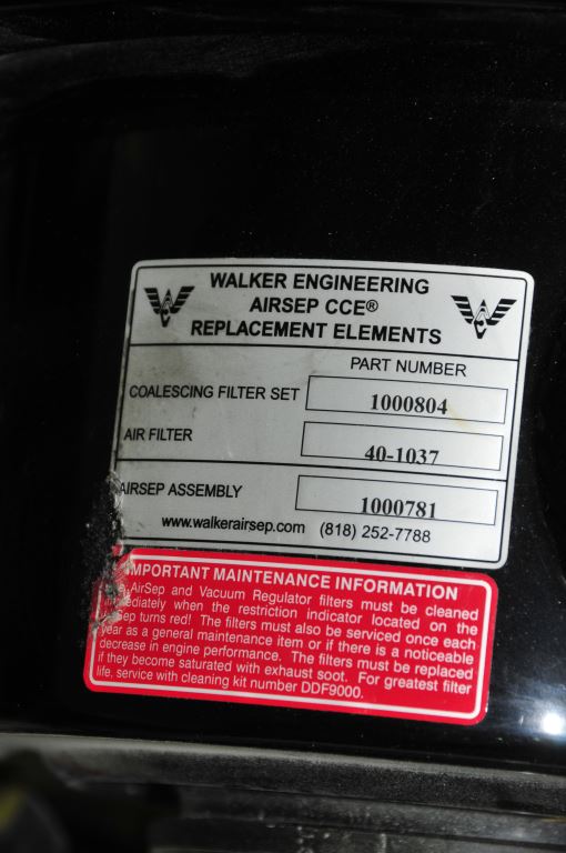
Most modern marine diesel engines are equipped with some form of closed crankcase ventilation, some of which are designed specifically by the engine manufacturer for that engine while others are off the shelf proprietary closed crankcase ventilation systems. The latter often include more features, greater efficiency and serviceability as well as more sophisticated oil recycling systems that are particularly good at coalescing oil vapor back into liquid. Some units include a monitor window that alerts the user to a restriction and need for cleaning or replacement of the cartridge or coalescing element, as well as another indicator that alerts the user to the need to replace the air filter element itself.
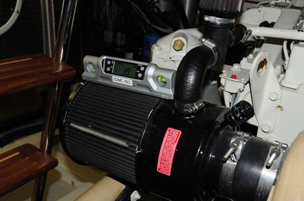
An added benefit of many crankcase ventilation systems is the addition of an air filter vacuum monitor, which alerts the operator to the need for element replacement. Such filter monitors can be added to many air filter housings, even those that don’t benefit from after-market crankcase ventilation systems.
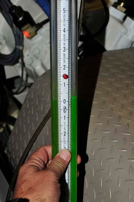
A burden tube manometer is sometimes used by mechanics to check both crankcase and exhaust system pressure.
Although it’s not a necessity per se, most engines and engine rooms both old and new will benefit from the installation of a proprietary closed crankcase ventilation system and many engine manufacturers now include off the shelf brands as standard equipment. They can reduce carbon build up within the combustion chambers and reduce oil consumption as well as helping to maintain engine efficiency.
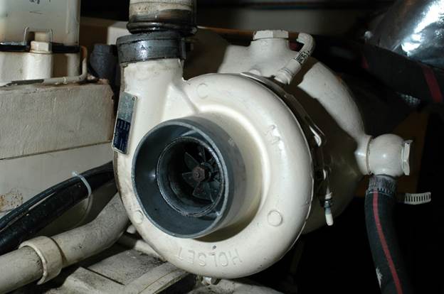
A potential source of increased crankcase pressure that’s often overlooked, leaking turbocharger seals should be checked before assuming high pressure is the result of other internal engine wear or damage.
It’s important to note that a closed crankcase ventilation system is not a cure for excessive blow by or crankcase pressure. If the engine is worn and blow by is fouling the air filter and intake manifold with oil or frothy, melted milkshake-like ooze, then it’s time a visit from a mechanic or, possibly, an engine rebuild or replacement.
Installing a CCV on an engine in this state is tantamount to balancing bald tires. Crankcase pressure can be easily measured by a mechanic. This test is performed using a manometer, while the engine is under load (it cannot be accurately performed while dockside). This test should be carried out of excessive blow by is present, as well as during a pre-purchase inspection, it can provide a window into the operating condition of the engine. In addition to worn piston rings or glazed cylinder walls, excessive crankcase pressure may also be the result of leaking turbo-charger seals, which can leak exhaust gasses into the crankcase via the oil return plumbing. If high crankcase pressure is identified, all of these possibilities should be investigated.
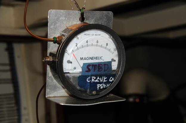
Crankcase pressure gauges are also available in an analogue dial format, like the one shown here. The typical unit of measure for these and slack tube manometer is inches of water. This one has a range of 0-10. While it varies with engine manufacturer, a maximum allowable crankcase pressure of four inches of water is not unusual.
A final note on CCVs, it’s critically important that they be installed properly and to the letter of the manufacturer’s instructions. An improperly installed crankcase ventilation system could do more harm than good by, among other things, allowing unfiltered air to enter the engine or in some cases by allowing large amounts of oil to be sucked into the air intake.
Crankcase ventilation systems are far from set and forget, they must be monitored and regularly and serviced periodically. A blocked or fouled crankcase vent can lead to oil leaks as well as damage to crankshaft seals.
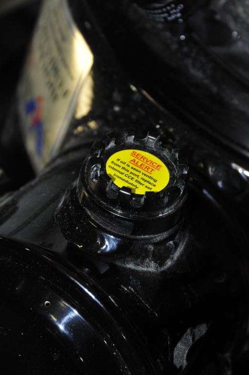
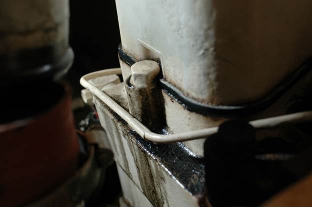
Depending on the unit, some crankcase ventilation system manufacturers call on users to be alert for venting of oil, like the one shown here, while others rely on a window into which a red sleeve is pushed if the unit becomes restricted.
If your vessel is equipped with a closed crankcase ventilation system inspect it to make certain it was installed properly, even if it came from the factory and be certain you fully understand its service needs and indicators, and be sure to service it in accordance with the manufacturer’s instructions.