Deciphering the Ingress Protection Code – Editorial: Alaska’s Lituya Bay
From the Masthead
When you read this, I will be cruising in Southeast Alaska aboard the Fleming 65 Venture. As I write this, we are the sole vessel anchored in Lituya Bay, renowned for the massive 7.8 earthquake-induced landslide (90 million tons), and ensuing 1,700-foot mega tsunami, the tallest ever recorded, which took place here in July of 1958. In addition to killing five people, two did survive, a fisherman and his 7-year old son, who have provided eyewitness accounts. The wave decimated much of the forest surrounding the bay, and to this day the line it described is still visible because of the new growth alders that replaced the legacy conifers (in this region, when landslides wipe out old growth trees, if allowed to grow back naturally, alders are the pioneers). Through the study of tree rings and other evidence on the shore, it has since been determined that events such as this, generating waves as high as 490 ft., have occurred on at least three previous occasions, in 1854, 1899 and 1936.
The Bay is also known for the crew of two whale boats who were lost here, part of a French expedition. It was visited in 1786 by Admiral Jean-François de Lapérouse, who named it Port des Français; his boats were lost with 21 of his officers and sailors; against his orders, they entered the inlet at a tide that was ebbing into a strong ocean swell, which created a boiling, tempestuous cauldron (the bay must be entered, and departed from, with great caution, ideally at slack or only at carefully planned intervals); the boats capsized, they were swept out to sea and all were lost, with no trace of them or the craft ever found. There is a land mass in the center of the fish-shaped bay, Cenotaph Island, meaning “empty tomb”, named with clear intent by Lapérouse, and on which there is a memorial dedicated to those who were lost from that expedition.
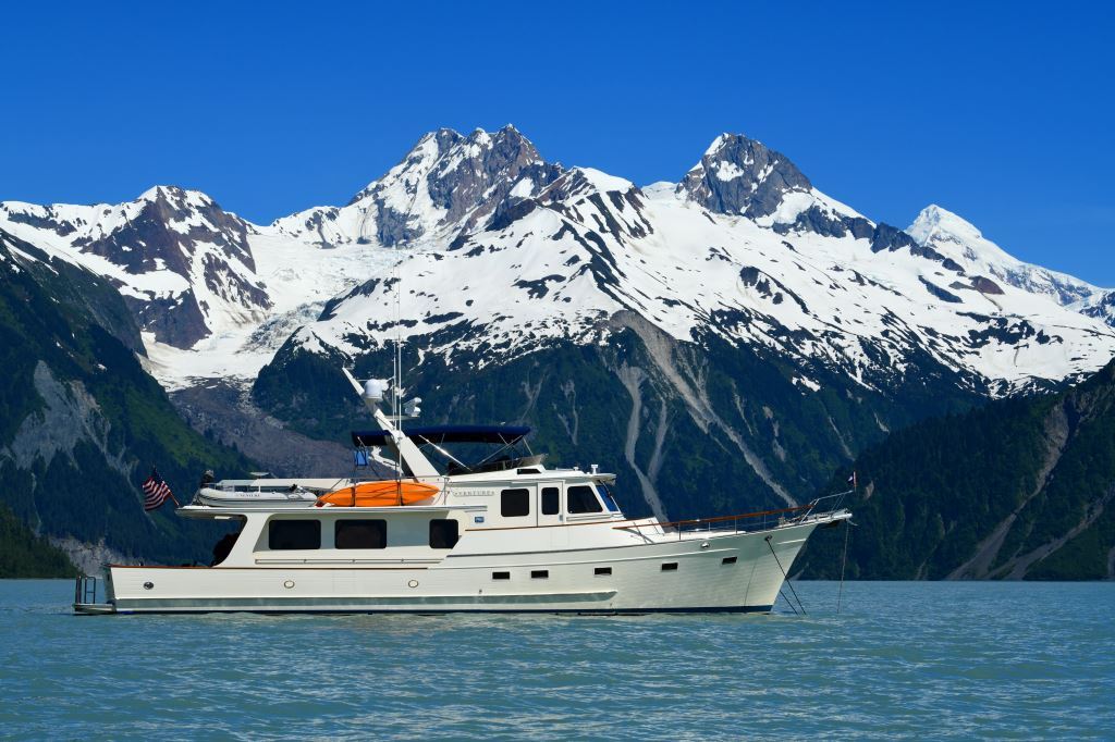
With Southeast Alaska’s Fairweather Range as a backdrop, Venture lies at anchor in Lituya Bay. The massive rockslide occurred on the mountain face just to the left of her transom.
Describing Lituya as ‘spectacular’ simply doesn’t do it justice; towering snow-encrusted mountains, glaciers, fog, waterfalls, moose, bear, and otter, again all to ourselves, make this a very memorable anchorage.
I’ll be aboard through mid-July, and shortly after my return to civilization I head to Taiwan to inspect a nearly-completed new build project. This will be my first trip back to this region in two years. My last trip, in August of 2020, required a 14-day hotel room COVID quarantine upon arrival; that has now been reduced to just three days, and thus far more manageable. I’ll report on this trip upon my return, as well as writing a feature-length article about the Alaska adventure aboard Venture.
This month’s eMagazine feature article covers the subject of ingress protection, I hope you find it useful and interesting.
Deciphering the Ingress Protection Code
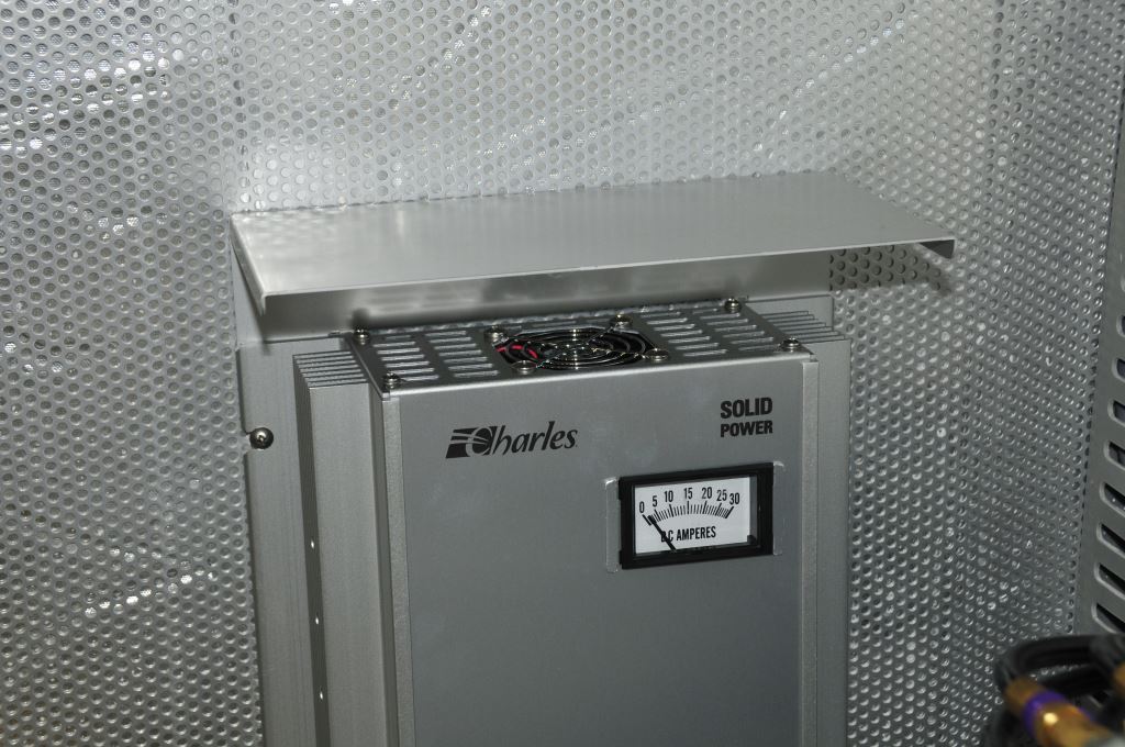
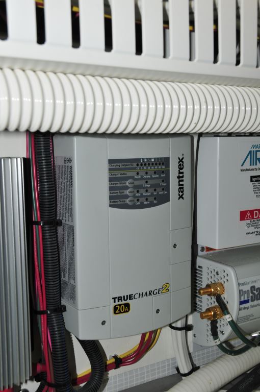
This battery charger manufacturer includes a drip shield as a standard component.
The Rules
Several years ago I became aware of the American Boat & Yacht Council’s (ABYC’s) requirement for drip protection in Chapter A-31, “Battery Chargers and Inverters.” Section 31.5.5.2.1 states that chargers and inverter/chargers shall be installed “in a ventilated, dry, accessible location,” while 31.5.5.5 dictates that “physical protection from falling objects or drippage shall be provided unless such provision is integral to the unit” (italics mine). And, 31.5.5.3.4 adds still more, saying that a charger and/or inverter must “be mounted at least 24” (0.6m) above normal accumulation of bilge water, or protected so it is not subject to bilge splash.” I must confess, before reading this I simply assumed that manufacturers of marine battery chargers and inverters built in protection from that virtually inevitable onboard phenomenon, dripping water. That is decidedly not so, all one has to do is look at the gaps and holes in the tops and sides of many of these components.

Drip protection may not be intuitive, some component manufacturers require installation at an atypical angle; so be sure to familiarize yourself with the installation instructions.
The Code
Other than these obvious water-ingress avenues, how is one to know if a particular piece of gear is protected from dripping water, or if an external deflector is required? (Note that A-31 also calls for chargers to meet UL 1236, which includes drip-resistance requirements; therefore, a charger that complies with UL 1236 should, in theory, be protected from dripping water. If your eyes tell you otherwise, then you should be suspicious.) Enter the IP Code, or International Protection Marking System, often (logically) referred to as “Ingress Protection.” While it’s not referenced specifically in ABYC A-31, the standard, published by the International Electrotechnical Commission (IEC), provides those who select and use this gear with an indication of resistance to access through the chassis, as well as resistance to water. The two-number IP code system is in widespread use and covers everything from simple junction boxes to cell phones. You’ve almost certainly seen—and probably ignored, as I initially did—these numbers when perusing installation manuals and online specifications.
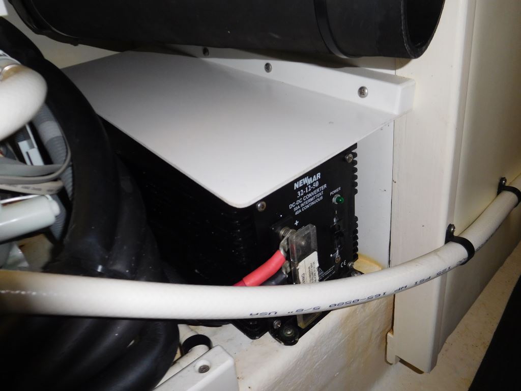
This DC to DC converter could be considered a battery charger of sorts; it is equipped with a drip shield.
Here’s how it works: The first numeral (0-6) essentially specifies the size of the largest object that could fit through openings or gaps in the component’s enclosure, starting at no protection against ingress, i.e., an open, unenclosed device (0), to openings that would allow the back of a hand (1), fingers (2), tools and wires (3), insects (4), and ultimately, dust-tight (6).
The second numeral (0-9) is where it gets interesting. Starting again with no protection against harmful ingress of water (0), then moving up to resistance to vertically dripping water (1), dripping water when the device is tilted up to 15° (2), spraying water (3), and the highest rating, being able to resist a powerful jet of high-temperature water (9K). See the tables below for specific details, including the duration of these tests.
While this isn’t part of the ABYC Standard, the IP code system can serve as a guideline for installers who are attempting to comply with A-31. If no IP code is present, then you’ll have to follow your judgment and the manufacturer’s written descriptions. If clear openings are present in the top or upward-facing surfaces—and, in some cases, sides (a hole in the side of an enclosure could potentially admit water, while a louver may shed it)—then clearly the component, out of the box, is not compliant. Given my druthers where IP ratings for chargers and inverters are concerned, I’d like them to meet IP 22 or 32.
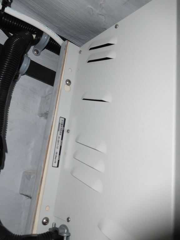
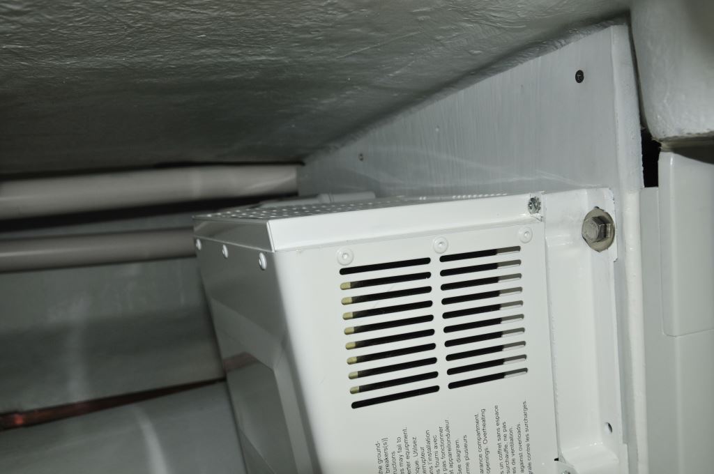
Louvers like the ones shown here can shed water, however, the cord grip beneath these is not water resistant.
Table 1: Solid Particle Protection
| Level | Protection against object sized | Effective against |
| 0 | — | No protection against contact and ingress of objects. |
| 1 | >50mm | Any large surface of the body, such as the back of a hand, but no protection against deliberate contact with a body part. |
| 2 | >12.5mm | Fingers or similar objects |
| 3 | >2.5mm | Tools, thick wires, etc. |
| 4 | >1mm | Most wires, slender screws, ants, etc. |
| 5 | Dust protected | Ingress of dust is not entirely prevented, but it must not enter in sufficient quantity to interfere with the satisfactory operation of the equipment. |
| 6 | Dust-tight | No ingress of dust; complete protection against contact (dust-tight). A vacuum must be applied. Test duration of up to 8 hours based on airflow. |
Table 2: Liquid Ingress Protection
| Level | Protection against | Effective against | Details |
| 0 | None | — | — |
| 1 | Dripping water | Dripping water (vertically falling drops) shall have no harmful effect. | Test duration: 10 minutes
Water equivalent to 1mm (0.04”) rainfall per minute |
| 2 | Dripping water when tilted up to 15° | Vertically dripping water shall have no harmful effect when the enclosure is tilted at an angle up to 15° from its normal position. | Test duration: 10 minutes
Water equivalent to 3mm (0.12”) rainfall per minute |
| 3 | Spraying water | Water falling as a spray at any angle up to 60° from the vertical shall have no harmful effect. | Test duration: 5 minutes
Water volume: 0.7 liters (0.18 gal) per minute |
| 4 | Splashing water | Water splashing against the enclosure from any direction shall have no harmful effect. | Test duration: 5 minutes
Water volume: 10 liters (2.6 gal) per minute |
| 5 | Water jets | Water projected by a nozzle (6.3mm) against enclosure from any direction shall have no harmful effects. | Test duration: at least 3 minutes
Water volume: 12.5 liters (3.3 gal) per minute |
| 6 | Powerful water jets | Water projected in powerful jets (12.5mm nozzle) against the enclosure from any direction shall have no harmful effects. | Test duration: at least 3 minutes
Water volume: 100 liters (26 gal) per minute |
| 6K | Powerful water jets with increased pressure | Water projected in powerful jets (6.3mm nozzle) against the enclosure from any direction, under elevated pressure, shall have no harmful effects. | Test duration: at least 3 minutes
Water volume: 75 liters (20 gal) per minute |
| 7 | Immersion, up to 1m depth | Ingress of water in harmful quantity shall not be possible when the enclosure is immersed in water under defined conditions of pressure and time (up to 1m of submersion). | Test duration: 30 minutes
Tested with the lowest point of the enclosure 1,000mm (39”) below the surface of the water, or the highest point 150mm (6”) below the surface, whichever is deeper. |
| 8 | Immersion, 1m or more depth | The equipment is suitable for continuous immersion in water under conditions which shall be specified by the manufacturer. However, with certain types of equipment, it can mean that water can enter but only in such a manner that it produces no harmful effects. The test depth and/or duration is expected to be greater than the requirements for IPx7. | Test duration: continuous immersion in water
Depth specified by manufacturer, generally up to 3m |
| 9K | Powerful high-temperature water jets | Protected against close-range high-pressure, high-temperature spray downs.
Smaller specimens rotate slowly on a turntable; larger specimens are tested freehand for a longer time. Smaller specimens are tested from 4 specific angles. There are specific requirements for the nozzle used for the testing. |
Test duration: 30 seconds in each of 4 angles (2 minutes total)
Water volume: 14–16 liters (3.7–4.2 gal) per minute |
Solutions
If you find that a component lacks an IP rating or is otherwise not compliant with ABYC A-31, all is not lost. You can install a relatively simple “rain shield” over the component. Sometimes these are available from manufacturers as accessories. If made in-house, this will be no more than a section of a metallic or acrylic sheet (the latter is flammable and could pose a fire hazard in the event the charger or inverter overheats or catches fire, many inverter and charger manufacturers call for installation on non-combustible surfaces, and all manufacturer supplied hoods I’ve encountered are metallic), ideally up to an angle of 15° (the angle is my recommendation; it’s not specifically mentioned in the ABYC Standard). It should prevent water from running behind the gear, so the mounting flange may require bedding.
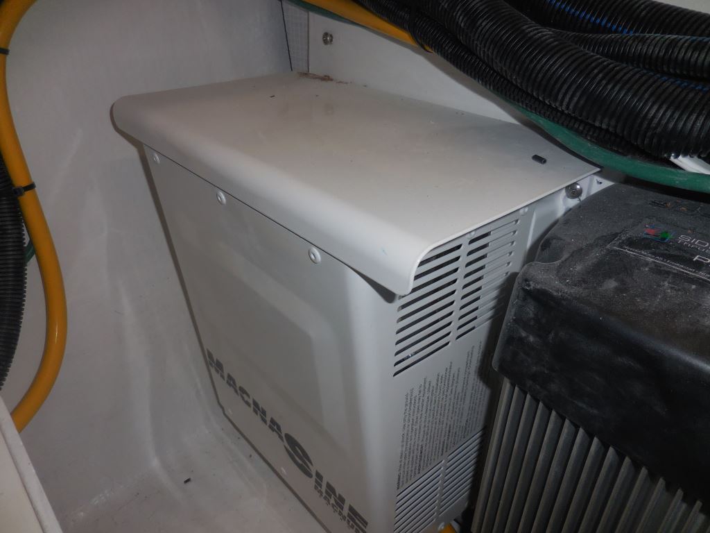
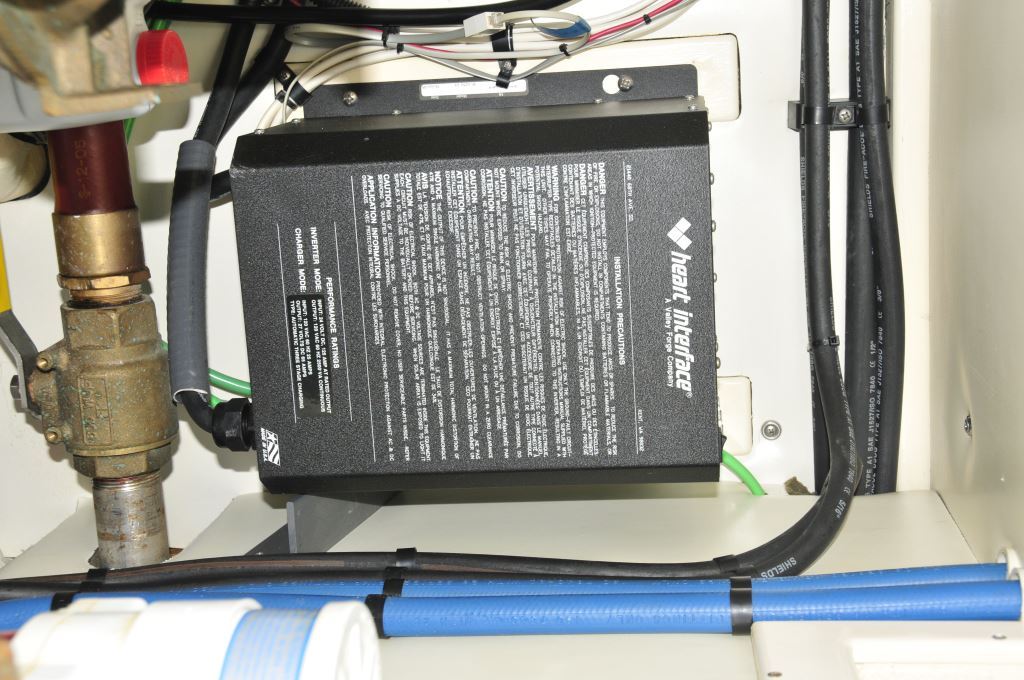
This inverter is equipped with an optional metallic drip shield supplied by the manufacturer. Note how it overhangs all of the sides.
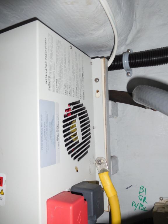
This inverter lacks a drip shield, its top and sides are louvered and thus open to water, and debris entry.
When it comes to protection from bilge water, obviously these units should be mounted well above (18”/0.5m or more) the level of water that would trigger a bilge pump. On a couple occasions I’ve seen chargers, inverter/chargers, and power converters being “showered” by leaking stuffing boxes while under way, or eater makers. Mounting these components in the path of a leaking packing gland or RO water maker is simply unwise and should be avoided, or shielding may be required.
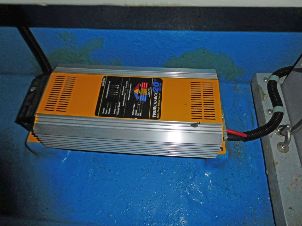
Battery chargers and similar electrical equipment should be mounted well above bilge water. While this unit rests on pedestals, they lack adequate height above the potential accumulation of bilge water; in this case another location should eb chosen.
While I’ve called out chargers and inverter/chargers, primarily because they are specifically mentioned in ABYC A-31, my recommendations apply elsewhere as well. For instance, ABYC E-11.14.4.1.1 states: “Junction boxes, cabinets, and other enclosures in which electrical connections are made shall be weatherproof, or installed in a protected location [hopefully, most boatbuilders and installers rely on the latter, unless the location is exposed to weather or bilgewater], to minimize the entrance or accumulation of moisture or water within the boxes, cabinets, or enclosures.” The definition of “weatherproof” according to E-11 is “constructed or protected so that exposure to the weather will not interfere with successful operation under the test conditions specified in NEMA 250, Type 3 or IEC 60529 Type IP 54.” Here, the IP rating is noted, which removes doubt and the need for interpretation.
While these inverter installations look professional, the enclosures are louvered on their top sides; both should be equipped with a drip shield.
Careful consideration should always be given to installation locations and drip protection for chargers and inverter/chargers, as well as for all electrical gear including transformers, converters, and junction boxes.