Editorial: IBEX 2026 Recap – Feature: Multimeters Part III; AC and DC Ampere Measurement and Troubleshooting
From the Masthead
IBEX 2026 Recap
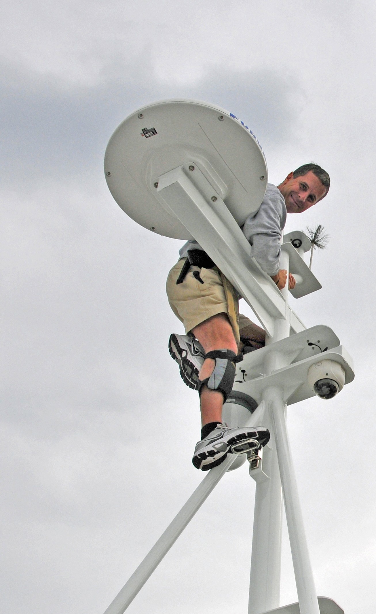
As is so often the case, I’m penning this month’s column while in flight, in this case high above the Bering Sea, on my way to Asia, where I’ll carry out in progress build inspections at three different yards.
I recently attended, and lectured at, this year’s International Boat Builders’ Exhibition, or IBEX, in Tampa, Florida. The show was well-attended, and the mood of most exhibitors I spoke with was positive and upbeat. The only damper, literally, was the weather, it rained every day.
This event is among my favorite, and one of two trade shows I attend religiously; the other being the Marine Equipment Trade Show, or METS, held each November in Amsterdam, the Netherlands.
Between lectures and meetings, I made a beeline for the show floor, where I soaked in as much vender interaction as my tired feet would bear. I met with both long-time colleagues, such as KBI’s Jim Burke, and Groco’s Dan Phalen, as well making new acquaintances, a sampling of which I have shared below.
I’ll share a similar report from METS, look for that sometime in December.
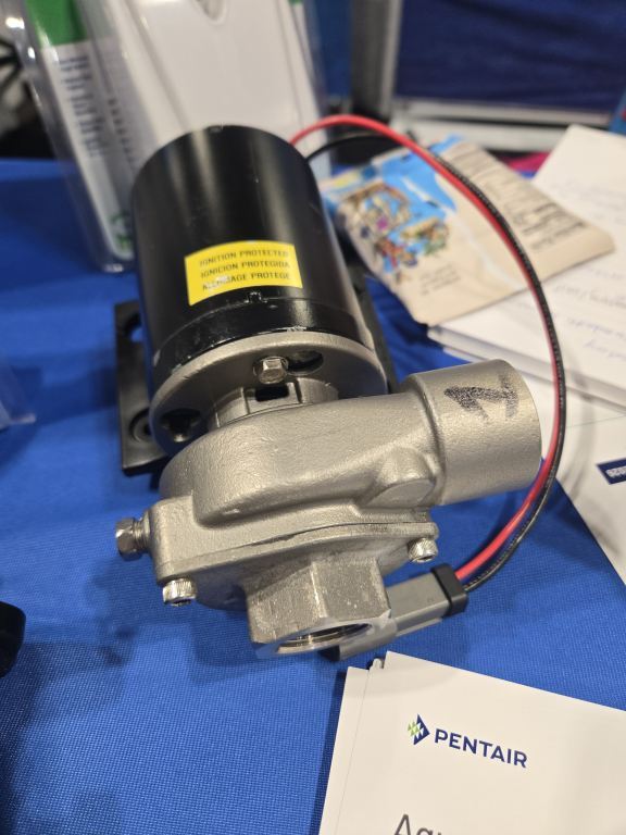
Pentair is offering a 120 VAC (they have a DC version as well), metallic impeller, raw water pump, in stainless steel and bronze, that would be ideal for cooling hydraulic system cooling.
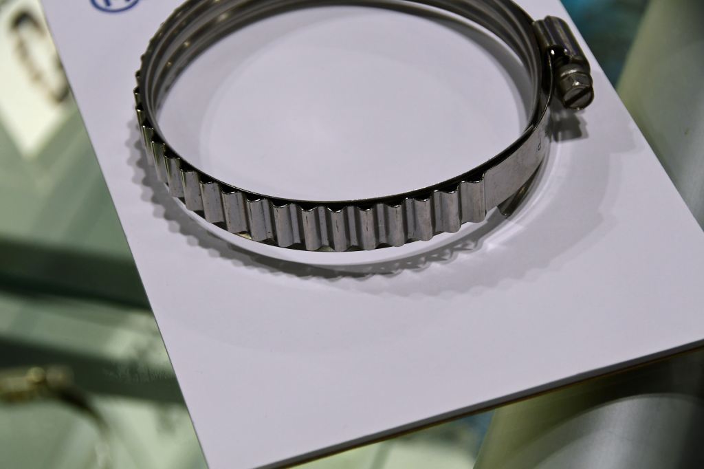
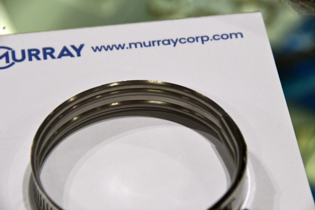
Murray hose clamps, include interior “beads” to improve compression, and an integral spring to maintain tension.
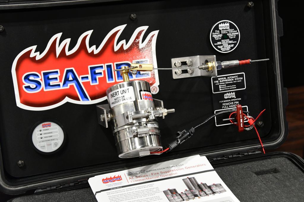
Sea-Fire continues to improve and refine its aerosol fixed fire extinguishing system.
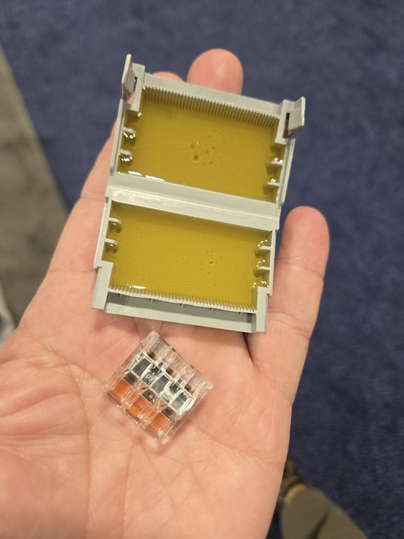
Wago is offering a water proofing encasement option for its already popular snap wire connectors.
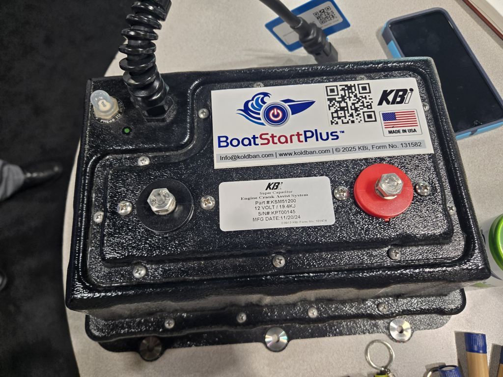 KBI’s super capacitor starting system has a new, more compact and smarter package.
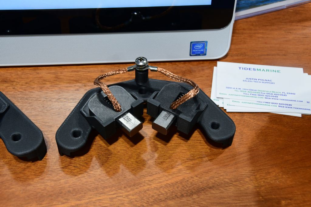
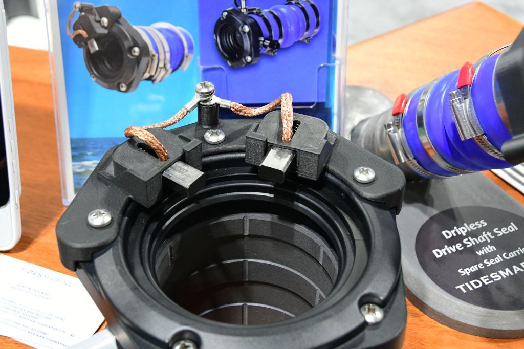
Tides Marine is now offering an integral shaft grounding brush for use with its SureSeal stuffing box.
This month’s Marine Systems Excellence column is Part III in the ongoing multimeter series. I hope you find it both useful and interesting.
Multimeters Part III: AC and DC Ampere Measurement and Troubleshooting
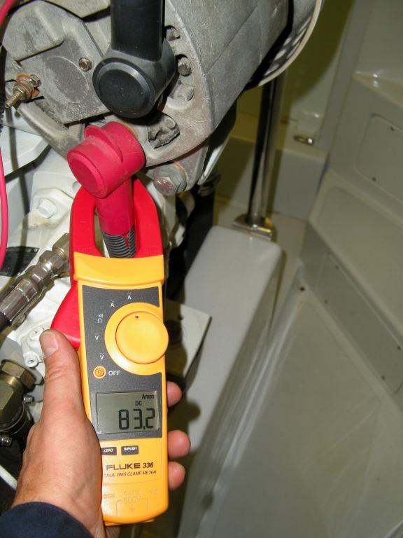
The most reliable means of measuring alternator output involves using an amp clamp. Voltage readings alone do not confirm how much power is being produced by an alternator, and volt meters used at alternator output studs can be fooled by other paralleled charge sources.
In the third of this ongoing series on the subject of digital multimeter use, I’ll touch on yet another function offered by this tool; that of ampere measurement.
An ampere, or amp as it is commonly abbreviated, is the aspect of electricity that does the heavy lifting. Sufficient amperage enables starter motors to overcome the compression and resistance of an engine’s pistons for cranking purposes, and it allows a high output alternator, whose output is typically measured in amps, to recharge a large battery bank relatively quickly. From a troubleshooting point of view having the ability to measure amps is invaluable, as it can enable the user to identify or isolate a variety of problems, from a malfunctioning voltage regulator to defective or shorted battery.
It’s critically important to differentiate the method by which amps are measured when compared to voltage. Last month I discussed how voltage is measured in parallel; that is the positive and negative test leads of the multimeter are placed on the positive and negative terminals of a battery for instance. Conversely, amperage is measured in series (see the Marine Systems Excellence article “Series and Parallel” here). When any electrical component is placed in series, be it a multimeter, light or battery, it is essentially inserted into a circuit rather than alongside it or in parallel. For measurement purposes, this means, up to about 10 amps, the multimeter becomes part of the circuit as a current carrying conductor. For example, if you wanted to determine how much current a bilge pump used, you would separate one of the pump’s conductors at the helm switch or electrical panel circuit breaker. Setting your meter to AMPS DC, you would ten attach one lead, it doesn’t matter which, to the wire leading to the pump, and the other lead to the energized conductor that ultimately travels to the source of power, the battery (these two conductors are referred to as the ‘load’ and ‘line’ respectively). When power is applied, the pump runs, and the meter will simultaneously indicate how many amps are being drawn. For this example, let’s say it’s a small 12 volt pump that is rated to draw 4 amps (larger pumps could draw more than10 amps, which is the limit of most multimeter test lead amp measurements). If, however, it’s drawing 8 amps, you might conclude that the insulation on the positive wire leading up the has chafed, or water has found its way into the pump motor, and is “leaking” current into the bilge water, creating a pseudo-short circuit. This will unnecessarily consume battery power and it may also create a stray current corrosion scenario.
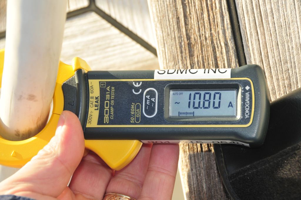
The ultra-sensitive clamp meter is registering over 10 amps of AC leakage current on this shore power cable. This is well above the 30 mA (30 one thousandths of an amp) threshold; it requires immediate closer investigation.
Most multimeters will safely carry up to 10 amps for measurements of this sort. Beyond that, however, their internal fuse should blow to prevent damage to its circuitry. For obvious reasons, try to avoid testing that function. What do you do then, if you want to measure the amount of current (current is another name for amperage) produced by the alternator, or consumed by the starter? Until a few years ago this was difficult to do, however, now it’s simple and easy, buy an amp meter that includes inductive amp clamp. The amp clamp, scissors-like jaws that can be spread and placed around a conductor, or conductors in some cases, enable you to measure hundreds of amps safely and easily, without ever touching or disconnecting a wire. It’s an extremely useful tool that I rely upon on a regular basis for troubleshooting and analysis purposes; and if your meter has an amp clamp option, it is unlikely you will ever use the test leads for measurement of current.
There’s one caveat to using an inductive amp clamp, if you wish to measure current, in most cases, the clamp must be placed around a single wire only. If you place it around several wires within a cable, like an AC extension cord, the hot and neutral conductors within the cable will neutralize the inductive field and the meter will read zero, or at least it should. If you place your inductive amp clamp around your shore power cable, for instance, it too should read zero. However, if it does not it may indicate a serious and potentially dangerous fault, which is allowing the water in which your boat floats to act as a return path for electricity. If that’s the case, unplug your boat from the dock and call an ABYC certified marine electrician to check the system for faults. More on that subject here.
On the other hand, there may be cases where you wish to measure current flow on more than one conductor, like the two “hot” AC wires supplying a 240 VAC appliance. In that scenario, encompassing both of those wires with the meter’s clamp will measure total current draw.
Next month, in the final installment of this series, I’ll review resistance, or ohms, measurement.