November 2022 Newsletter “Wiring Lithium-Ion Battery Systems”
Photo Essay: Wiring Lithium-Ion Battery Systems
Fires aboard vessels equipped with lithium-ion batteries quickly capture the attention of the boat building and cruising communities, and with good reason. Fire is perhaps the worst tragedy that could befall a vessel, with significant potential for injury and loss of life, not to mention property damage. The problem, however, is very few of these fires can be analyzed with any degree of certainty, in most cases the cause is never truly determined, only theories are put forth.
Lithium-iron phosphate, also known as LFP (F representing the Fe symbol for iron in the periodic table) batteries, while not the only type of battery used for house applications in recreational sea-going-applications, is the most common and it is also among the safest. Notably, it is different than the chemistries used in electric vehicles, Boeing 787s, phones, laptops and scores of other small battery-powered appliances. In fact, in comparing the Material Safety Data Sheets for LFP and AGM (lead acid) batteries, the former at least sound far less hazardous.
My own theory identifies LFP batteries only as an indirect culprit in these fires. Because LFP batteries are capable of accepting very high rates of charge, for extended periods, potentially much higher and longer than AGM batteries, the stress they place on electrical systems is significantly greater than the industry has been accustomed to, when using lead acid batteries (which again includes AGMs). Flaws in the electrical system, high resistance in high current connections in particular, that may have previously gone unnoticed, now become issues. High resistance married to extended high current flow, equals high heat production, which can lead to fire.
In the accompanying image, terminals on a new lithium-ion battery bank show an incipient but potentially fatal flaw. Heat shrink tubing has been applied to the terminals, to improve strain relief and resilience, however, that heat shrink material is impinging on the ring terminals’ current path, reducing the contact area considerably. This is tantamount to partially removing your shore power plug, while running air-conditioning, a water heater, and an electric range; once again with diminished contact area ampacity drops, while resistance, and heat production, increase.
Wiring associated with lithium-ion battery systems in particular should be designed and installed for minimum resistance, and closely and regularly inspected for anomalies.
Ask Steve
Steve –
I’m replacing my engine mounts this winter and noticed that one of the lag bolt holes securing the starboard rear engine mount to a stringer was stripped.
I’ve read your engine mount/alignment articles and understand that this isn’t the preferred way (lag bolted) to attach an engine mount but that’s the way the boat was built (the front engine mounts are through bolted to a heavy stainless bracket to the stringers). I see two possible repair options:
- Drill out the stripped hole, fill with epoxy resin (appropriate fillers added) and then re-drill for a lag screw
- Drill out the stripped hole and epoxy a 3/8”-16 stud in the hole. Leave 1-1 ½ inches of stud to accept the engine mount. There’s a lot of depth in the stringer to accept a long stud (6 inches maybe). This would seem a much stronger attachment than anything a lag bolt could achieve. I’d use a 316 stainless grade 8 Grade B8M threaded stud which is good for ~100,000 psi tensile strength.
Boat and engine parameters are as follows:
- 48’ Custom Bruce Marek sloop
- Yanmar 4JH2-TE (62 hp)
- Kanzaki KBW20 transmission – 2.62:1 reduction
- 20-inch Max Prop
I appreciate any insight and advice you can offer either on the above options or another option.
I am a former (lifelong) power boater having purchased Sola Fide in 2013 as my first sailboat (to own). I used to subscribe to a lot of boating magazines but have narrowed it down to one – Professional Boatbuilder, were I read many of your articles. Please keep up the great work.
Best regards,
Ron Kraus
Ron:
Ideally, I would like to see something more substantial than epoxy filling the old fastener hole. If you can manage it, drive the largest, thickened epoxy-coated, ash dowel into the former fastener holes that will fit, let the epoxy cure then drill a pilot hole and install stainless (fine for a small engine, for larger engines and higher loads I’d use corrosion-inhibited mild steel) lag bolts.
Epoxying a metallic stud in place has some draw backs. Chief among these is, while not impossible, it’s challenging to get epoxy to adhere to the metallic stud’s surface, particularly when one considers its small size and the torque loads. Preventing the stud from spinning when the fasteners is tightened will be challenging. Unless that stud can be threaded into an embedded metallic plate, or “wings” welded to it to prevent it from spinning, I don’t believe it will work, and if it does spin, you’ll have a hard time removing it.
Dear Steve,
I see “Hybrid Propulsion” has again become fashionable; I have recently read about a BAE System to be installed on a new Southern Wind build…
- https://www.marinelog.com/technology/superyacht-will-have-bae-hybrid-power-and-propulsion/
- https://gettozero.com/hybrigen_propulsion.php
I am interested in your thoughts if there have been any real advances in technology since similar systems were tried a dozen years ago – seems to me there are still a lot of power losses in BAE systems to overcome.
I seem to recall you had some involvement with the Electric Nordhavn some years ago– converting it to conventional drive?
Kind regards
Alan Sexton
Alan:
While I’m familiar with the Nordhavns that were built with hybrid diesel electric propulsion systems, I had no involvement with that projects, installing or reversing the installations; I was involved with converting a custom 74’ Greg Marshall aluminum trawler from diesel-electric hybrid propulsion to conventional diesel propulsion. Truth be told, I’ve been a sceptic of hybrid propulsion systems for two decades. Back in the early 2000s, when the first hybrid diesel-electric craze was overtaking the recreational power vessel field, I questioned its efficacy for two primary reasons. One, it’s highly complex, and highly complex, low production systems (like the one you have referenced) are more prone to failure (and I question the availability of long-term support), and being a former boat yard manager, I know how challenging it is to troubleshoot and repair complex systems. For vessels with full-time engineers, that may be less of an issue, however, for every-day recreational vessels, without professional crew, it’s another matter. Two, there is little if any net gain, converting rotational energy to electricity, and back to rotational energy, it is inherently inefficient, as is storing and then using electrical energy. There may be a narrow band of power under which a vessel may operate that yields single digit efficiency improvement, but at what cost, both literal and figurative? Finally, unlike electric vehicles, there is no energy to be recaptured when braking.
The system about which you’ve inquired is different in that when used on a sailing vessel power can be generated from a water turbine, a propeller that turns while the vessel is under sail, which makes electricity, and recharges the battery. The amount of energy that can be generated by these systems is limited, and they add drag, after all there is no free lunch, and so if the vessel finds itself in light airs, some other means of charging batteries will need to be available, solar, an auxiliary diesel generator etc. More on the subject here.
The day will no doubt come when a marine electric propulsion system is economically competitive, practical and reliable ; I just don’t believe that day is here yet.
Hi Steve,
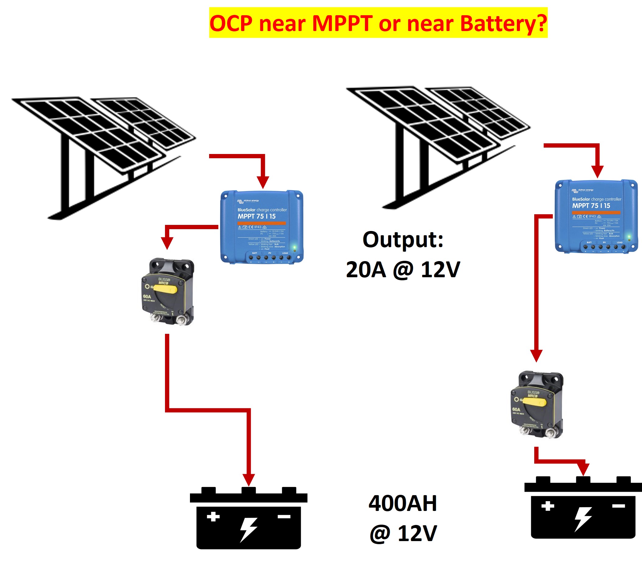
I am wiring a solar MPPT controller to charge a battery bank (12-volt system, MPPT would output 25-amps into a 600AH battery bank). My understanding is typically, OCP should be located close to the source, the MPPT in this case. But the battery bank has a massive discharge potential if there is a short or something.
Should the OCP be located closer to the battery? Both?
Thanks in advance,
Peter Pisciotta
Peter:
Over-current protection (OCP) should to be as close to the source, which is the battery, as possible.
Remember, the OCP protects the wire(s) so every inch of wore between a battery and OCP is unprotected.
Thanks Steve,
The “source” is the low-amperage MPPT, not the battery. I guess the question is, does the rule “as close to source as possible,” always apply even when there is a relatively high potential source downstream? See diagram below.
Sincerely,
Peter Pisciotta
Peter:
You must have OCP within 7” of the battery (72” if sheathed), period, no exceptions.
Re. the solar panel and regulator, ABYC’s language applies, particularly the part about “self-limiting devices”…
11.10.1.1.2 In addition to the provisions of E.11.10.1.1.1 the ungrounded conductors to a battery charger, alternator, or another charging source shall be provided with overcurrent protection within the charging source, or within seven inches (178 mm) of the charging source, based on the maximum output of the device.
EXCEPTION: Self-limiting devices.
11.4.30 Self Limiting Device – a device whose maximum output is restricted to a specified value by its magnetic or electrical characteristics.
NOTES:
- The output remains at a value or will automatically decrease to a value such that it will not damage the battery charger or inverter/charger after application of a short circuit at the output terminals.
- The output current will not exceed the ampacity of the conductor that is specified for connection to the battery charger or inverter/charger by the manufacturer.