August 2021 Newsletter “Full Throttle vs. Full Load”
Text and photos © 2021 Steve D’Antonio Marine Consulting, Inc.
Photo Essay: Full Throttle vs. Full Load
Sea trials are an opportunity to identify problems and defects in running and steering gear, as well stabilizers and overall vessel seakeeping. Many of these issues will be obvious; if for instance a vessel produces smoke under heavy load, or if there is too much resistance in steering, or an indication of air in the hydraulic fluid, all should be identifiable in a sea trial.
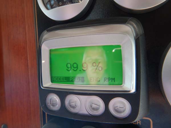
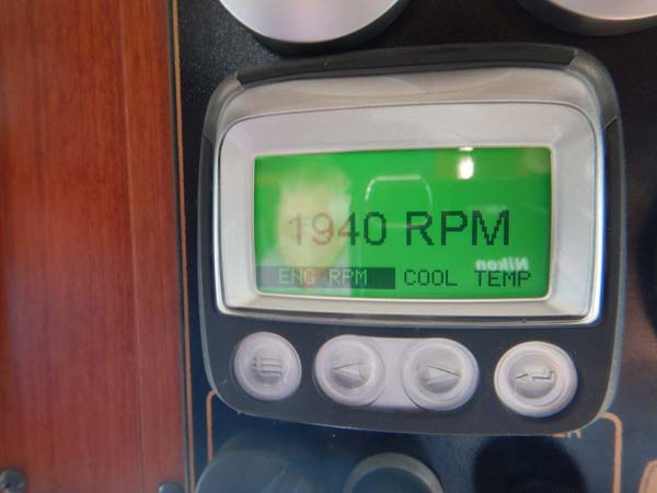
Some defects, however, are less obvious. In this case, I’ve pulled up three screens on an electronic engine display. One shows the percent of load, the other shows the percent throttle (or accelerator pedal as this is a system initially designed for over the road vehicles) and the third shows rpm. When pushing the throttle forward as far as it will go, wide open throttle, or WOT; the engine should achieve three goals; it should reach the maximum rated rpm (ideally 20-40 rpm more), it should reach 100% load, and it should show 100% throttle or pedal position. In this case it meets all but one of these goals, 92% load is an indication that the vessel’s propeller pitch, or diameter, or both, may be incorrect, and as a result it is reaching its governed, which in this case is 1940 rpm, rather than full load rated rpm (this engine’s full load rated maximum rpm is 1800). While it isn’t harmful to an engine to fail to reach 100% load, it does mean the engine is not producing the power for which it is rated, and for which the owner paid. Ideally, the pitch of this vessel’s propeller should be adjusted so that the load is at, or nearer, 100% while achieving the wide-open throttle rated rpm. There are other reasons why an engine might not reach full load rated rpm, to learn more see this article.
Ask Steve
Dear Steve,
I’ve read with interest your comments regarding crevice corrosion of stainless. I recently had an incident that called into question any available nondestructive testing that might be appropriate in these instances. We had a rudder that we were trying to determine if it needed replacing due to some corrosion where it had been inside the packing. Obviously an expensive proposition.
We have an 18 year old Ocean Alexander. I was getting some leaking at the rudder posts, the yard recommended taking the rudders out to inspect and reassemble with new packing. One of the rudders showed crevice corrosion where it had been inside the bearing. Oddly enough I had a spare rudder which they used, but the other rudder showed, albeit less, the same corrosion.
This had me questioning how this decision was going to be made, as fabricating a new rudder would have been quite expensive- hence my question about nondestructive testing. I understand that the rudder breaking would be a low probability high consequence event, but in fairness the economic part of this decision is also a consideration. Further, after bouncing around a lot of boat yards, I’m finally delighted with these folks and didn’t want to be seen as second guessing people with much more expertise then I possess.
Given all that, are there testing protocols that can be helpful in making a decision in cases like this? Thanks in advance.
Tim Tait
Tim:
Crevice corrosion is especially common on shafts, both propeller and rudder, at the packing material. More so on rudders as they move less, and they tend to be exposed to oxygen depleted water, an environment that’s a necessary ingredient for crevice corrosion.
In my experience, crevice corrosion removes material in an “erosion-like” format. Having said that, I’ve seen shafts that were laced with “worm holes”, making it difficult to know just how deep they’ve penetrated.
I know of no means of easily testing for corrosion depth, however, if the shaft is oversized for the application, some level of metal loss could be considered sacrificial, and therefore acceptable. Still, the rough surface would need to be taken into account, as it would no longer be suitable for making a seal with the packing. I’ve had success in moving the location of a stuffing box, by adjusting hose length, in order to reestablish the packing material to shaft seal over virgin shaft that’s not damaged by corrosion. Again, this approach would only be taken if the depth of the corrosion pitting was shallow.
Ultimately, I suspect you need to use your judgement, if the depth of the corrosion is deep enough to compromise shaft integrity, it would need be replaced or repaired by welding new material in place, called “cladding” and cutting on a lathe, and that decision, to repair or replace, would be driven by the cost of a replacement shaft. The cladding process is detailed in a sidebar in this article.
Steve,
You recently wrote about under water use of stainless steel. My first thought, would connecting the stainless part (in my case an exhaust pipe) to the boat’s grounding system/zinc help avoid the corrosion?
Secondly, on the removal of raw water impellers, I think that the puller with jaws is far better than prying, because when the prying is done it places a very high axial load on the shaft bearings. The jaw puller does not.
I enjoy your detailed articles about boats, which often leads to projects to make my boat better.
Thanks,
Joe Rieg
Joe:
Bonding disparate metallic interior plumbing to the vessel’s bonding system, and a zinc, would only be helpful if that plumbing was located on the hull, and submerged, and ideally had a line of sight to the zinc. Metallic plumbing within the vessel is afforded no galvanic protection, even if bonded. Bonding interior plumbing can help reduce the likelihood of stray current corrosion for submerged components, i.e. a fitting that is immersed in bilge water. Of course below the waterline through hull fittings/seacocks should be bonded.
For more on this subject see here and here.
As far as impeller removal, indeed, the axial puller with jaws is the preferred approach for impeller removal. Prying, if used, should only employ non-metallic “pry bars”. There’s little chance of damaging bearings with this method, however it is possible to damage the gasket surface of the pump body if a metallic pry bar or screw driver is used. Yet another method is a hose pliers, which has a pincer-like jaw, like these.
Hello Steve,
I’ve been reading your articles for some time and you do a great job.
I see a boat I like in the UK, it’s a 50 Hz boat and I want to bring it back to the US. Can you comment on the complexity and cost of converting it to a 60 Hz boat? For world cruising do you want the capability to accept shore power at both 50 and 60 Hz, and should that be factored into the design?
Thank you for any thoughts.
John Bradley
John:
This question has been posed many times, and with good reason. The world is flat and getting flatter, including where cruising vessels are concerned.
As far as the actual mechanics of plugging devices in aboard, there are universal receptacles that allow you to plug in virtually any male plug configuration. These would be applicable for devices that are not voltage or frequency sensitive, like laptops, tablet and phone chargers etc. These can, however, be very dangerous if misused (and they are non-ABYC compliant) plugging a 120 volt 60 Hz hair dryer, or flattening iron into 240 volts 50 Hz would be a memorable experience, one that’s best avoided. With these plugs, it becomes easily possible.
Beyond that, however, you’d need to convert frequency and voltage.
How that can be done has so many possible options (and sub-variations for 50 Hz vessels operating in a 60 Hz environmental, and 60 Hz vessels operating in a 50 Hz environment) that would require a more detailed response than is possible here. If you were to operate this vessel in North America, on 60 Hz, the dockside voltage, 240 volts AC, could be correct, but not the frequency, and for frequency-sensitive gear like some motors and compressors, as well as clocks (in microwave and conventional ovens for instance), as well as electronics in some appliances etc., it could pose problems, some of which would be more than a simple nuisance, they can lead to equipment damage and overheating.
Servicing and getting parts for 50Hz appliances in North America could also pose some challenges.
The biggest issue, load-wise, is HVAC. If the compressors and air handlers are variable frequency, then that’s solved, they can operate on 50 or 60 Hz, however, some HVAC manufacturers call for a slightly different voltage when operating on a frequency for which the unit is not primarily designed, this is almost always posted directly on the air handler or compressor frame (and this would be achievable with a transformer). (This is frequently seen on 120 volt HVAC gear designed for use in 60 Hz environments).
The washer and dryer present the next challenges, the latter especially because of its heavy load. If they are not 50/60 Hz capable, and they probably aren’t, then that hurdle has to be overcome as well.
The next issue would be refrigeration. While they may exist, I’ve seen no household refrigerators or freezers that are specifically designed and warranted to operate on 50 and 60 Hz. You could try it and be prepared to replace the appliance(s) if it fails. However, you’d still be supplying it with 240 volts, so you’d need to replace it with a 240-volt model, or install a local step down transformer. Some builders use US spec 60 Hz refrigerators on 50 Hz vessels by installing local transformers to step the voltage down to 100 volts, which offsets the frequency difference. However, that can be an issue for refrigerators that have frequency sensitive electronics.
If the vessel is equipped with an isolation transformer (and it almost certainly should be for this type of application especially) then you would need to ensure it is rated to operate on 50 and/or 60 Hz, this is by no means a certainty. If the HVAC shore power line is not equipped with a transformer, and most are not, it should be equipped with one as well, however, it would not be mandatory if everything on that service was 240 volts and rated for both 50 and 60 Hz.
If the vessel remains 240 volts, as opposed to 120/240 VAC, for use of 120 volt gear, small appliances etc. you could install a 120 volt inverter and 120 outlets in select locations, or use the 120 volt tap from an isolation transformer to supply these circuits. Access for wiring will drive some of this decision.
A complete conversion from 230 VAC 50 Hz to 120.240 VAC 60 Hz may require significant re-wiring. Depending on the manufacturer, vessels wired for 230 VAC use smaller wires because they can, as the current is lower. If you convert to 120 VAC, higher current would flow, requiring larger wires, and essentially a new electrical panel. Some builders who wire vessels for both 50 AND 60 Hz, use the larger 120 VAC wiring for both models, which would simplify the conversion. Even if this is the case, you’d still need significant rewiring of the panel; this route is usually cost prohibitive, and is therefore rarely taken.
Finally, you could simply install a frequency converter. These essentially accept 120/240 VAC 60 Hz and convert it to 240 VAC 50 Hz. It’s a simple solution, however, they are large, costly and generate heat, all of which would affect your decision making process. You would still need to make provisions for 120 VAC aboard, for small appliances.
As you can see it’s no small undertaking. It is, however doable. For more on the subject see this article.
Greetings Steve,
For the past year I’ve been sailing and fixing up a 1969 Bristol 33.
Your article about engine mounts was extremely informative. I really appreciate your attention to detail. I thought you might be able to tell me what (if any) my options might be for low-profile engine mounts.
I’m attempting to fit a Yanmar 3GM30F into the bilge’s engine area. The original Atomic 4 was decidedly rusted-up when I bought the boat. The Yanmar won’t sit low enough to align the prop shaft with the factory mounts. The space is too narrow. They also seem a bit squishy.
If it comes to it I might try making some mounts with rollerblade wheels or cast-able urethane, but I thought I’d ask your advice before going to such extremes. For now I will work on building new stringers. If I use flexible mounts, they need to be no more than 2″ tall. Do such things even exist?
Any thoughts are appreciated, even if you’d rather tell me to scrap the whole project and start over with a different engine (or boat!)
Engine-less sailing has treated me very well. I’m tempted to just make oar-locks for the winches and maybe do an electric conversion, but a diesel engine seems hard to beat.
Best,
David Earle
David:
The Bristol 33 is a venerable vessel, it seems as if this one is in good hands.
Yanmar motor mounts are especially high profile. I’ve never researched it but I assume Yanmar believes this is necessary to absorb vibration from these small three cylinder engines. Never the less, there are alternatives. Here are two…
- http://www.pyiinc.com/downloads/r-d-marine/r-d-marine-yanmar-engine-mount-price-list.pdf
- http://www.polyflex.com.au/mounting-systems/product/207-y-2ctf-mount
Two inches, however, is a mighty tall, or short, order, I’m not sure either of these will fit, and still allow room for adjustment. If you opt to make your own you’ll need to incorporate a means of adjustment, even if that’s just the insertion of shims. These engines are particularly “lively”, so if you make your own you’ll likely be transmitting some of that movement to the vessel. You might find this article on the subject of engine alignment useful as you work through this project.