
Text and photos by Steve D’Antonio
Copyright © 2017
From the Masthead
As I write this column I’m in flight just south of Greenland, on my way to attend the Dusseldorf Boat Show (I packed my New Zealand possum wool socks and gloves, it’s forecast to be in the low 20s).
A few years ago I carried out an inspection aboard a 50+ foot vessel on the East Coast. After the engine surveyor arrived we prepared to get underway. Something, however, was wrong. I’m accustomed to seeing moving blankets stacked high with plastic tool boxes and bags containing these mechanics’ tools of the trade, gauges galore, multi meters, wrench and socket sets, manometers, pyrometers etc. This mechanic, however, traveled very light, in fact he carried nothing. I asked him where his tools and monitoring gear were and he said, “I don’t need anything, the engine’s instruments tell me everything I need to know”. I knew at that point this would be a long sea trial.
While underway I shut down the generator and as soon as I did the engine’s volt meters, which register the condition of the starting batteries, began to drop, clearly the alternators were not functioning properly. I brought this to his attention, yet he seemed unconcerned. When it dropped to 11.8 volts I reached my tolerance for risk, I re-started the genset and brought the charger back on line. Throughout the day he regaled those aboard with sea stories and tales of his marine conquests (there were lots of confrontations, in which he always prevailed). He never visited the engine room. At one point after returning to the dock he lost his temper and threatened to leave the boat because the surveyor, a squared away and knowledgeable young man, in an effort to avoid soiling furniture, carpeting and upholstery, changed shoes and knee-pads each time he left or entered engineering spaces. This level of attention to detail somehow offended his sensibilities. Everyone aboard was on edge. The shame of it is, this mechanic was knowledgeable, whenever I managed engaged him in gearhead talk, between tall tales, he offered thoughtful, detailed responses. However, it was also clear to me, he’d decided long ago he had learned all he was going to learn, there was room for no more information on his hard drive. He was a textbook example of a mechanical prima donna, and because of this it’s unlikely anyone would be willing to share new information with him, he effectively isolated himself.
The marine industry is in dire need of knowledgeable, experienced folks with the right attitude. We have little room for those who know it all. The professionals in this industry who I respect are the ones who never stop learning, as much as they know, there’s always room for new information, techniques, products, always time for another perspective or nugget. Above all else, they are curious.
The folks working on your boat should embody some of this spirit, including and especially the curiosity part. If you are an industry professional, ask yourself this question, “Am I receptive to new ideas and information, and is that the message I convey to those around me?” If the answer is ‘no’, you are missing out, and are in danger of becoming a prima donna.
This month’s Marine Systems Excellence eMagazine article covers motor mounts, the often overlooked and frequently neglected heroes of the engine room. I hope you find it both useful and interesting.
The Engine Room’s Unsung Hero; Motor Mounts
A couple of years ago I came across one of those, ‘it looks good but it’s seriously wrong’ scenarios. These can be very challenging because those who are responsible for them are often reluctant to accept that they may be flawed, because they look right.
I crouched down alongside the engine and took a good long look at the motor mounts, and the longer I looked, the less I liked what I saw. The mounts were over-extended, a common problem that I’ll discuss in greater detail below, and their bases were not parallel with the engine’s centerline, so much so that one end of the mount’s flexible section was in compression, while the other was in tension, or at least not evenly tensioned. Furthermore, the weight of the engine was not evenly distributed; some mounts were bearing more of the engine’s weight, and thus were more compressed, than others, which can cause, among other things, vibration issues. In spite of appearances, this installation was insidiously problematic.
Ties that Bind
Take a moment and think about what connects the thrust created by your vessel’s propeller to the vessel itself. There’s the propeller shaft of course and the transmission and the engine. All of those components are, however, isolated from the hull by one, small, relatively simple component; the motor mount (referred to by some as an “isolator”). With the exception of systems using thrust bearings, motor mounts are the sole means of interface between the power created by the engine and the vessel, enabling it to move. If they are improperly installed or ill-maintained, then their functionality and reliability can be called into question.
The motor mount’s saving grace is its simplicity; it typically has only two moving parts, the adjustment and locking nuts that enable it to be used as a fine tuning device of engine alignment. Coarse adjustment is carried out during the vessel design, initial engine installation and if necessary thereafter with shims located between the mount bases and the stringers.
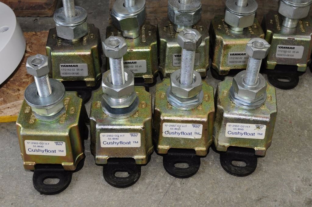
The typical motor mount consists of a cast or forged aluminum or steel foot (at least one manufacturer’s is non-metallic, reinforced plastic), which is affixed to the vessel’s hull or stringers using machine screws or lag bolts. Within this base or foot is a rubber-like or polyurethane, vibration absorbing pad or ring, some of which are considerably more sophisticated than others. The threaded stud rests on top of or within the rubber, offering it a degree of isolation from the metal base and the stringer.
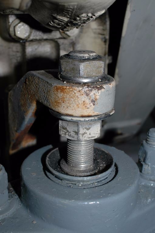
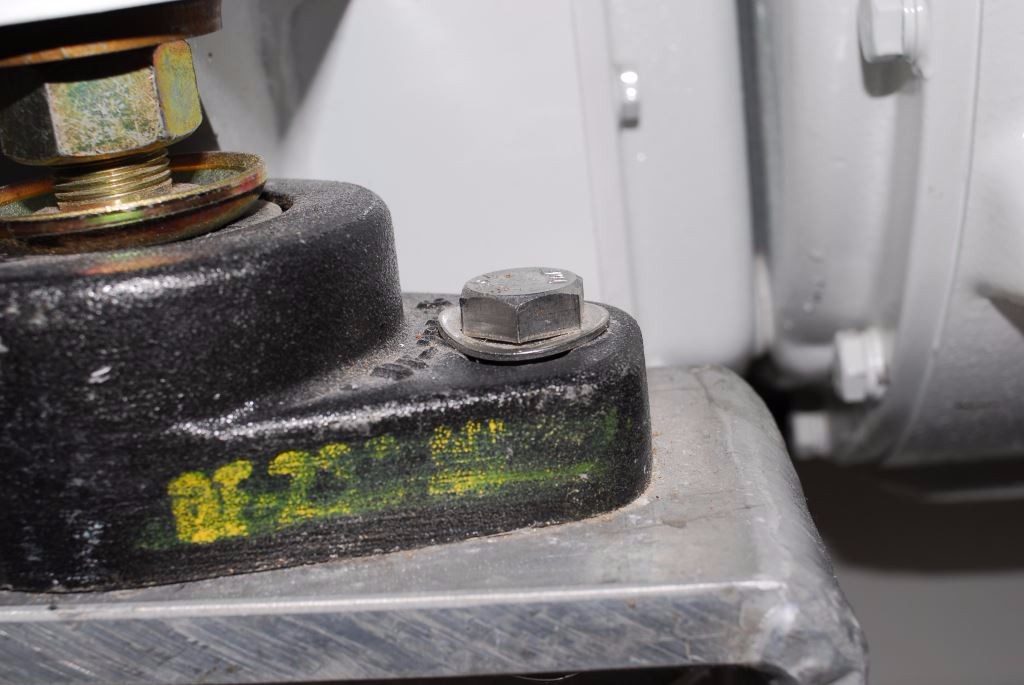
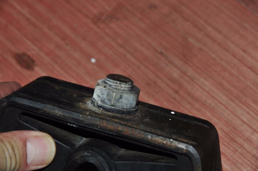
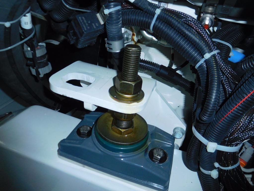
The engine’s bracket or foot should reside somewhere in the middle of a motor mount’s stud. This one is at the limit of its upward adjustment, exposing the mount to excessive load thanks to the added leverage.
How they Work
In the days of timber vessels, engines were bolted directly to stringers. While the wood helped absorb some of the vibration, it was imperfect at best, alignment was achieved with wedges or shims, making adjustment difficult. Today, proprietary, pseudo-flexible, adjustable mounts carry out two vital missions. First, they should be designed to absorb some of the vibration created by the engine and running gear. Second, with once again the exception of vessels that are equipped with a thrust bearing system, motor mounts must also absorb the aforementioned thrust created by the propeller. Carrying out both of these tasks well is a tall order. Absorbing vibration requires suppleness (a “soft” durometer) in a motor mounts flexible component; however, absorbing thrust invariably compresses a portion of that flexible material, thereby enabling the transmission of vibration. It’s a compromise at best.
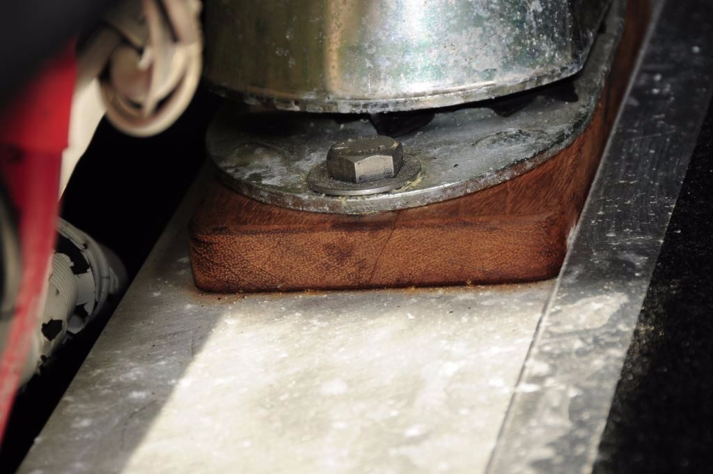
Because of its compressibility and propensity to crack, timber, even teak, is not a suitable material for shimming motor mounts.
Additionally, while under way, resistance from the propeller causes an engine to attempt to rotate in the opposite direction, thereby compressing the mounts on one side of the engine more than the other. In some cases, for smaller engines, the mounts on the non-compressed side may actually go into tension, i.e they are being lifted by the engine’s reaction to the propeller. For this reason, some engine manufacturers specify mounts of differing durometer for the right vs. the left side of the engine, a detail that is critical, and often missed, for those carrying out mount replacement.
Motor mounts are available in a wide range of sizes, capacities and durometer, and with varying mechanisms for improving their ability to absorb both vibration and thrust, while a handful include a means of measuring the load placed on them, for balancing purposes. Most are exceedingly simple, relying on a cast in place hunk of rubber to fulfill these roles. Others are more complex, and more costly, with designs that allow progressive absorption of movement and compression that’s based on thrust load. While there are exceptions, most come with little or no documentation.
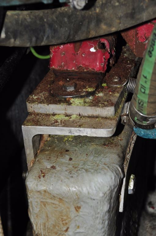
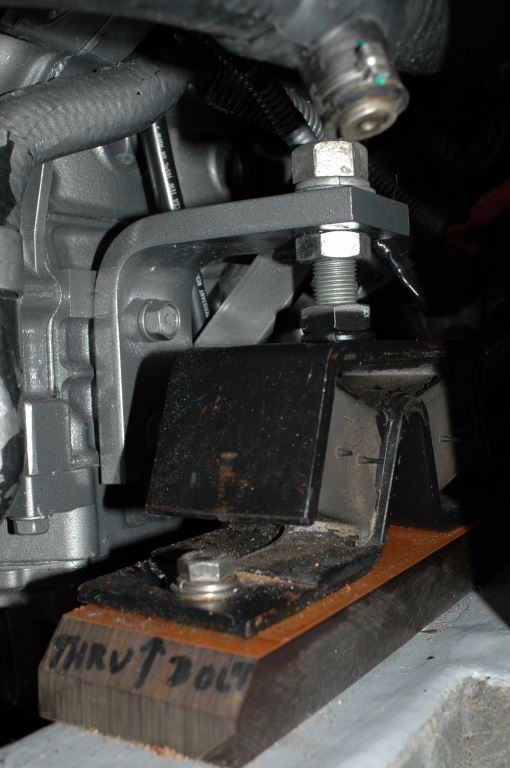
Even with the best of intentions, there are many ways a motor mount installation can go wrong. In this case the most egregious is the cantilevered “diving board” support bracket. Not only is this prone to failure, it’s also likely to compound vibration.
More sophisticated mounts also typically require specialized knowledge where installation and adjustment are concerned. One brand, Barry Controls – Hutchinson, includes a two page installation “manual”; reading it is a must for every installation and subsequent adjustment. In the vast majority of cases when I encounter these mounts, I’m able to determine with a quick visual inspection of their “snubber gap”, which is designed to assist installers in balancing motor mount loads, that their installation instructions have not been followed; i.e. they have not been adjusted properly. I like these mounts, I believe they are very effective, however, if they are not installed properly then you’ve paid for performance you aren’t getting. PolyFlex is another mount manufacture that provides detailed selection and installation documentation with their products, as well as excellent factory support.
Installation
Even the highest quality mounts will yield poor service if installed incorrectly. Among other requirements, engine beds or stringers must be square with the engine installation, i.e. the surface on which the mount is installed must be parallel with the engine crankshaft centerline (the oil pan flange can often be used as a visual reference; when carrying out an analysis I use a digital level to measure the angle of the stringer’s surface, and compare it to the angle of the engine bracket), and the mount’s adjustment stud must be perpendicular with the engine bracket or foot to which it is attached. Unless the engine is level, unless its centerline is parallel with the stringers’ surface, then wedges will need to be installed under the mount bases. Ultimately, the engine bracket must be parallel to the mount bed surface in both planes.
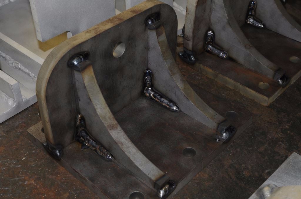
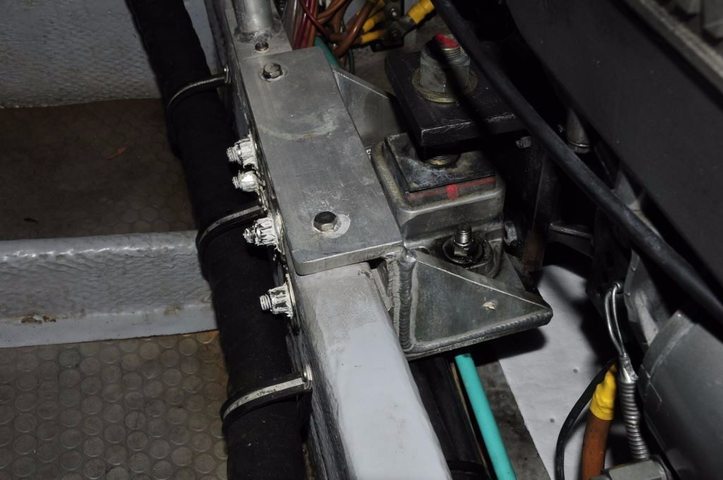
If a motor mount cannot be installed directly on a stringer, then a bracket must be fabricated. Brackets must be heavily built, and inflexible. The ones shown here are in the process of being fabricated to support a 790 hp engine.
Some mount manufactures recommend that the mounts be installed as close as possible to the crankshaft centerline. From a thrust, as well as seaway and rolling perspective doing so is advantageous, however, this positioning is not adjustable, it is a function of the design of the engine bracket or foot, placing it into the engine manufacturer’s or dealer’s purview, or that of the boat builder.
The stringers should be equipped with metal inserts with tapped holes or nut inserts, or capped with channel steel or aluminum to accept bolts or machine screws. While many smaller power and sailing vessels rely on lag bolts screwed into fiberglass or timber (or timber or foam cored fiberglass), this approach is problematic and less than reliable, through bolts and machine screws are preferred. Fasteners used for mount installation should be suitable for the loads that will be encountered, which means most power vessels will require grade 5 or grade 8 mild steel, rather than stainless, bolts and thicker than standard, deformation resistant washers. Mild steel fasteners must be corrosion inhibited.
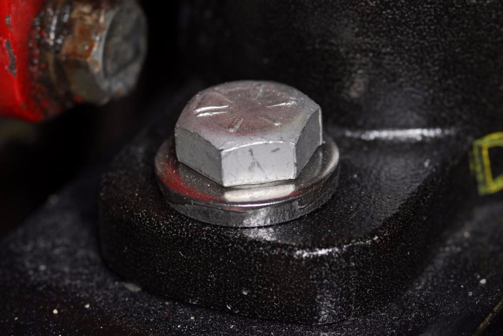
Standard, thin fender washers (top) and stainless steel bolts simply lack the necessary rigidity and tensile strength for use in many motor mount applications. The heavy duty thick washer (above), and grade 8 bolt, shown here provide the necessary support for the anticipated loads.
Unlike conventional thin washers thick, beefier washers are able to resist deformation under the very heavy loads to which motor mount hardware is subject. Because many mounts include an athwartship adjustment slot, fasteners that secure mounts to stringers should also be equipped with heavy duty, deformation-resistant washers. Any deformation in motor mount washers is too much, look carefully at yours and upgrade them if necessary.
Make sure all fasteners associated with motor mounts are installed over surfaces that are free of paint. Under heavy compression paint can crack or be squeezed out from under fasteners over time, leading to loss of tension; use a torque wrench to tension all motor mount fasteners, including and especially the upper adjustment locking nut.
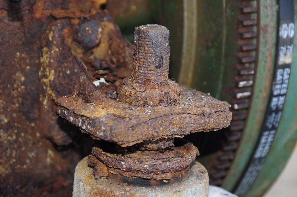
Over-extension (top) is a common issue with motor mount installations; often leading to failure of the stud (above). In spite of the composite shim that has been added to this mount, the problem remains.
Among the most common mount installation faults involves the aforementioned over-extension of adjustment or leveling studs. The adjustment stud allows the installer to account for small variations in alignment between the transmission’s output coupling, and the propeller shaft coupling, with emphasis on the word ‘small’. Ideally, and most motor mount manufacturers are clear about this, once alignment is complete, the engine bracket, which is supported by the adjustment stud, should reside somewhere near the mid-point of the stud, allowing for future adjustment, and not at the extreme maximum or minimum height of adjustment, with the former presenting more of an issue than the latter. The higher the bracket is on the mount’s stud, the more leverage that is applied from the propeller’s thrust, the more stress placed on the stud, and the greater the likelihood of failure. If the engine bracket will end up too high on the adjustment stud, the mount should be shimmed using a robust, non-compressible material such as steel, aluminum or fiberglass or epoxy sheet laminate such as GPO3 or G10 respectively. Do not use wood of any variety, or non-reinforced plastic such as UHMW, often known by one of its manufacturer’s names Starboard. These materials are prone to compression and fracture.
Additionally, it is vitally important that the diameter of fasteners used to secure the mounts to the stringers or support brackets match the diameter of the mounting holes in the mount bases. If the fastener is undersized, it can allow the mount to shift when the gear is placed into forward and reverse (more likely if the mount rests on a polished stainless steel stringer cap). If necessary, the gap can be filled with bushings, or a two part shimming material like Chockfast. If the mount bases are plastic, as many now are, they are more prone to shifting in this scenario; with all other installation parameters remaining the same, this often happens when plastic mounts are used to replace metallic mounts.
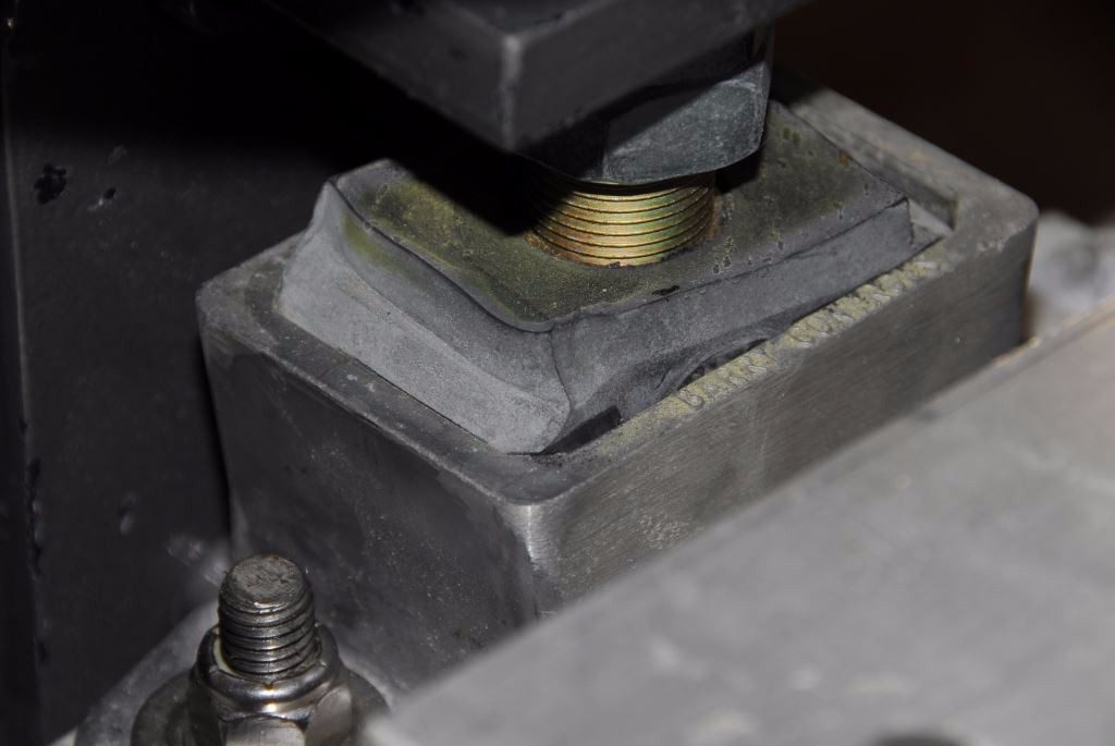
This mount is failing because it has been installed incorrectly, the surface on which it rests is not parallel to the engine’s bracket in both planes, causing the rubber insert to deform.
I once went aboard a 47 foot sailing vessel to carry out engine service and was astonished to find that three of the four mount studs had broken, the engine was teetering in place, being retained by the remaining stud and the propeller shaft.
Mounts must also be installed in such a way as to avoid caster (toe in toe out) or camber (“rocking” or tilted inboard or outboard). They must be upright and parallel to the engine support bracket and stringer, preferably within 4° in all directions.
If the engine bracket is slotted, when initially installed the mount should be positioned so that the stud is centered in the slot, again allowing room for adjustment. The same is true of the motor mount base, in many cases one of the two mounting holes is slotted; it should be installed so that the supporting fastener is initially in the center of the slot.
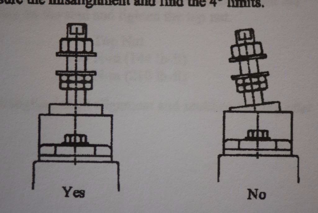
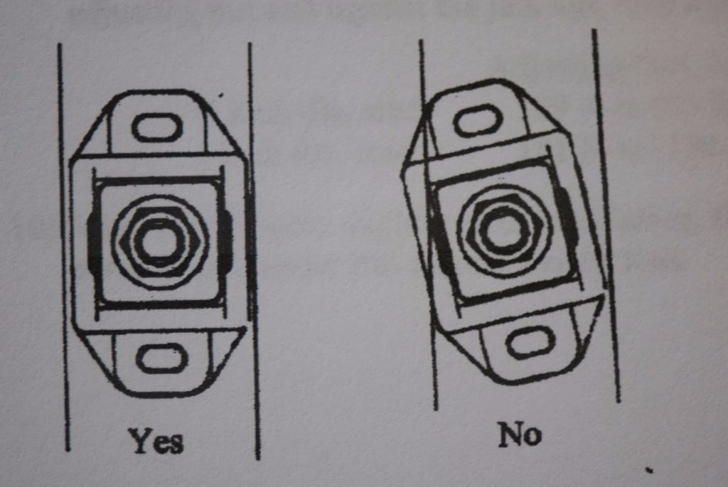
Avoid toe and camber when installing motor mounts, adjustment studs must be perpendicular with the engine bracket, and the mount base must be parallel with the crankshaft centerline and stringer or shim surface (diagrams courtesy Barry Controls).
They are Adjustable
In addition to ensuring that the engine remains firmly attached to the vessel in which it’s installed, the motor mounts perform another vital function; that of engine alignment or adjustment. Rotating the adjustment nut on the mount stud (these threads should be lightly oiled to prevent galling, however, anti-seize compound should never be used) enables a mechanic or savvy do-it-yourselfer to move any one of the engine’s four corners up or down as necessary, in order to properly align the shaft coupling with the transmission output coupling.
Motor mounts and their brackets should be gusseted, to prevent flexing, and through bolted.
More sophisticated mounts include two stages of adjustment. One involves alignment; the other has an effect on the amount of load carried by the mount. Unevenly loaded mounts can actually induce rather than mitigate vibration. Where conventional mounts are concerned load is difficult to determine. For ‘designer’ mounts, on the other hand, a load indicator is incorporated into the mount, enabling an installer, in addition to carrying out alignment, to properly balance load across all four mounts, or at least fore and aft, a desirable feature to be sure, as is emphasized in this excerpt from the Barry Controls installation manual, “Adjusting the height also adjusts the share of the weight carried by each mount. It is very important to equalize the weight of the engine and gear on each of the isolator mounts as much as possible so that each mount carries its share of the load. In some situations the load cannot be completely equalized between the forward and aft mounts, but the load should always be equalized between the port and starboard sides of each engine.”
If more of the engine’s weight is born unevenly, particularly diagonally across two mounts, the engine can “teeter”, which in turn can lead to severe vibration. This phenomenon can be caused by incorrect mount adjustment, during the alignment process, or in the case where mounts’ flexible material deteriorates, tears or collapses. While it may not be immediately obvious this is occurring, measuring and comparing the clearance between the mount’s base and floating portion can be helpful in identifying the culprit; overloaded or collapsed mounts will have less clearance.
Once alignment, and load equalization where applicable, is complete, locking nuts should be tightened up to the adjustment nuts using two wrenches, holding the adjustment nut steady, while tightening the locking nut up to it. Failure to use two wrenches will frequently result in a loose adjustment nut, and misalignment, as insufficient tension is created between the two nut surfaces.
Corrosion is an ever present issue where motor mounts are concerned. The base of this mount is made from composite, it will therefore never rust. The adjustment stud has been coated with a film corrosion inhibitor that dries to a wax-like consistency. Note the aluminum shim beneath this mount.
Once the alignment is set it may need one additional check to account for settling, thereafter it rarely has to be adjusted and herein lies the problem. With disuse, any mechanical component can become balky and motor mounts are no exception. You may find, when the day comes where the engine alignment must be adjusted, the mounts are frozen solid with years of accumulated corrosion. Inspect your mounts for rust, make sure they are free of rust and corrosion, and then spray them liberally with a corrosion inhibitor to keep rust at bay. Some petroleum based lubricants and rust preventatives may attack the mount’s rubber shock absorber (if exposed, some designs incorporate an “oil shield” or umbrella); avoid them or use with caution, avoiding application onto the flexible component. I prefer a ‘tacky’ product such as CRC Heavy Duty Corrosion Inhibitor, as it will neither run into, nor attack rubber.
Motor mounts are adjustable and while they may not need to be adjusted often, they must be kept free of corrosion and in good working order.
Inspection
Check all mount fasteners, those used for adjustment as well as those that attach the mount base to the vessel’s stringers, and the mount bracket to the engine or transmission. For casual inspection simply run your fingers over all of these and feel for any movement. Mount fasteners are notorious for loosening, deforming, rusting and stripped threads.
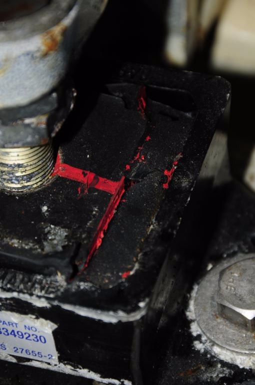
This motor mount utilizes a telltale red core to signal that it’s reached the end of its life. In many cases a failure of this sort is the result of an installation error.
Inspect the visible portions of rubber shock absorbing material on your mounts. If they show any signs of cracking, crumbling, shedding of dust or separating from the metal, it’s time (probably well past time) for their replacement. Some higher quality mounts utilize a color indicator to draw attention to failing flexible material, the outside portion is black while the core is red, if you see the latter then the mount has effectively failed, frequently because of improper installation.

