
Text and photos © 2021 Steve D’Antonio Marine Consulting, Inc.
From the Masthead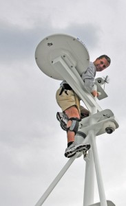
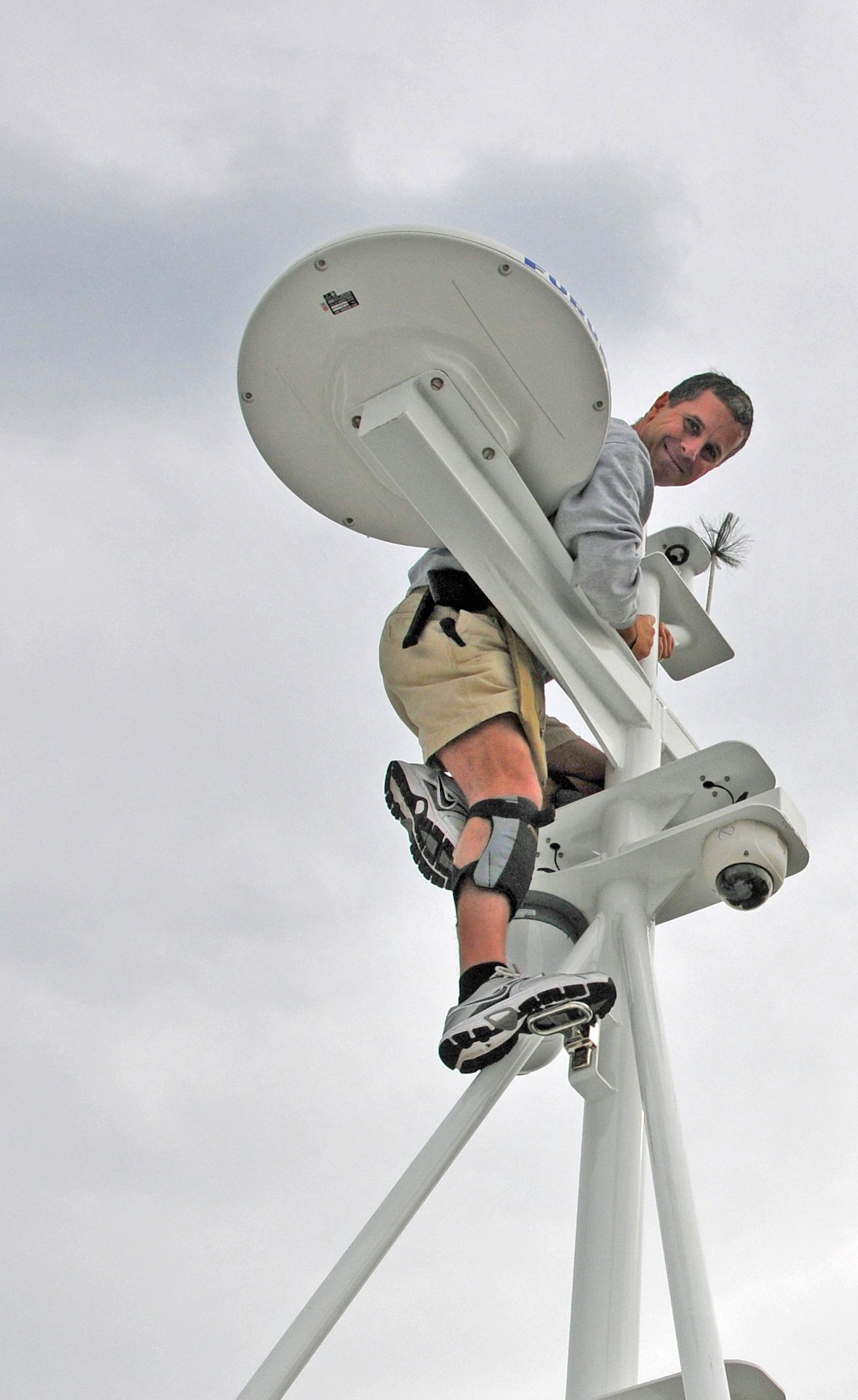
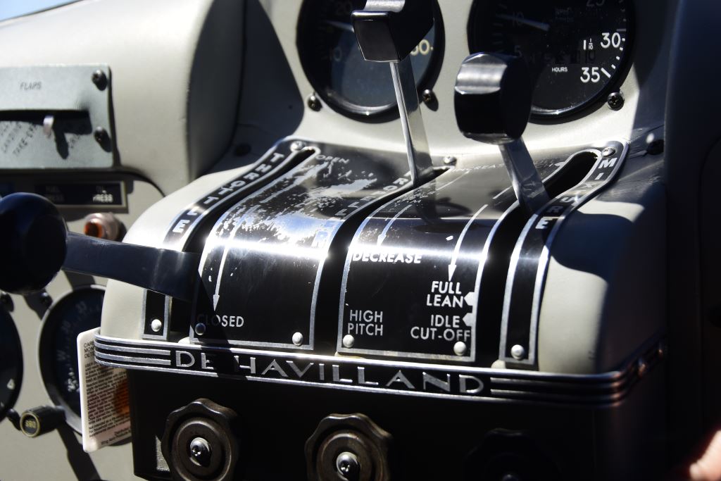
I recently made a flight aboard a de Havilland DHC-2 Beaver, a seaplane manufactured in 1959. It’s in commercial service and flies almost every day. The art deco-inspired cockpit is a study in simplicity; gauges and controls are well-refined, accessible and easy to service. The Beaver’s Pratt and Whitney R985 9-cylinder radial engine is music to the ears of any antique aircraft enthusiast or gearhead; there’s just something about the deep reverberation of a radial engine, almost 40,000 of which were manufactured between 1929 and 1953. Think about that, the aircraft was built in 1959, and its engine was built before 1953, and both are safely flying paying passengers around Puget Sound, British Columbia, Alaska and elsewhere.
About 1,600 Beavers were produced between 1947 and 1967. They quickly developed as a rugged, go anywhere bush plane used by forest services, cargo haulers, crop dusters and passenger services. Nine DHC-2s are still in service with the United States Civil Air Patrol for search and rescue purposes.

The reason the Beaver has endured for so long is simple, it’s rugged and relatively simple, which means it can be kept in service economically, even commercially, which is the acid test. Can the same be said of any small craft, is there an equivalent of the Beaver afloat? I’d like to say yes, but I’m struggling to come up with one. As an industry, are we now building any small craft, recreational or commercial, that will endure and thrive 50 or 60 years into the future?
This month’s Marine Systems Excellence eMagazine article covers the subject of corrosion analysis. I hope you find it both useful and interesting.
Reference Cell Testing; Know Thy Corrosion Protection Level
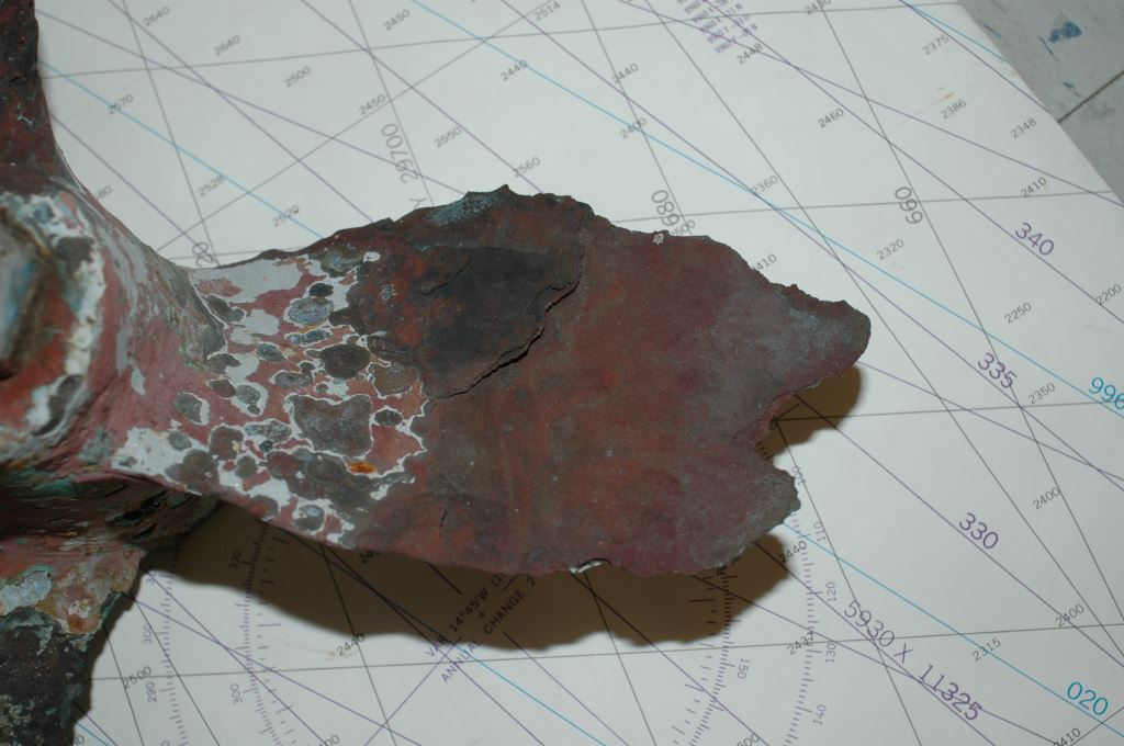
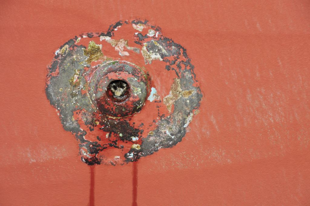
Stray current corrosion is vicious and rapid, it can destroy a propeller like this in a matter of days. While sacrificial anodes may do little to prevent it, a reference cell can be used to help identify its presence and the source.
I recently read a post by a boat-owner on a sailing forum, in which he was puzzled about why his zincs “…only lasted 6 months”, he was soliciting opinions. My advice for him was straightforward enough, ‘While this time frame doesn’t seem unusual, instead of guessing, or listening to internet sages, about how long zincs should last, carry out a reference electrode test, it’s easy and definitive.’
Anodes
Zincs, I’ll refer to them as anodes from now on, since they can be made from one of three metals, zinc, magnesium or aluminum, are consumed based on the load placed on them, which is affected by many factors, including salinity, temperature, current, the amount, and type, of metal they are protecting and the condition of the vessel’s bonding system and shore power isolation.
In a process known as ‘cathodic protection’, sacrificial anodes are used to protect underwater metals. These anodes should be replaced when 50% depleted (using more anode mass will equate to longer intervals between replacement, but can also lead to over-protection, more on that below). As the anode is consumed, its protection level drops, so trying to squeeze more life out of it is not good corrosion prevention etiquette. Furthermore, if anodes last too long something is probably wrong; they may not be making good contact with the metal they are protecting, the bonding system may be in poor condition, they may be substandard (e.g., non milspec composition for instance) or they may be the wrong metal for the application; zinc, for instance, does not work well in fresh or brackish water.
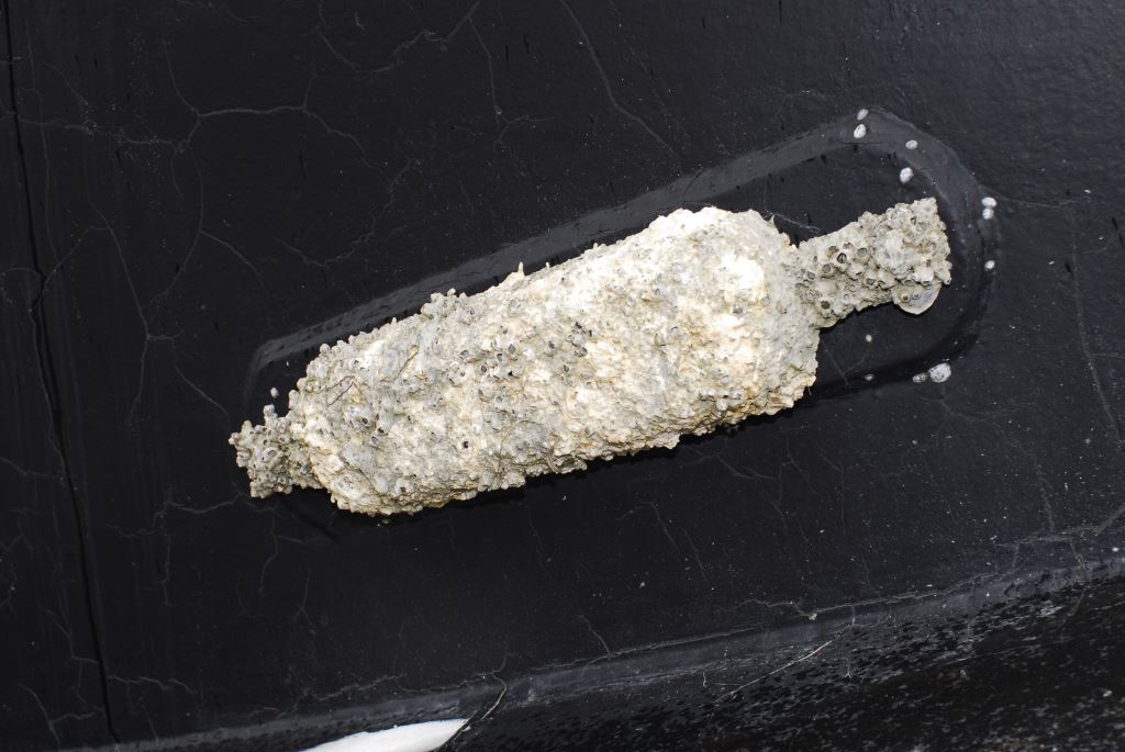
Anodes that seemingly last forever, or those that actually support marine growth like that shown here, are dormant, and thus providing no protection to underwater metals.
Not long ago, on another forum, a vessel owner complained that his stern thruster anode was being consumed far more quickly than the one used on his bow thruster. He included photos and they told an interesting story, the bow thruster anode was almost pristine, while the stern thruster anode was mostly consumed.
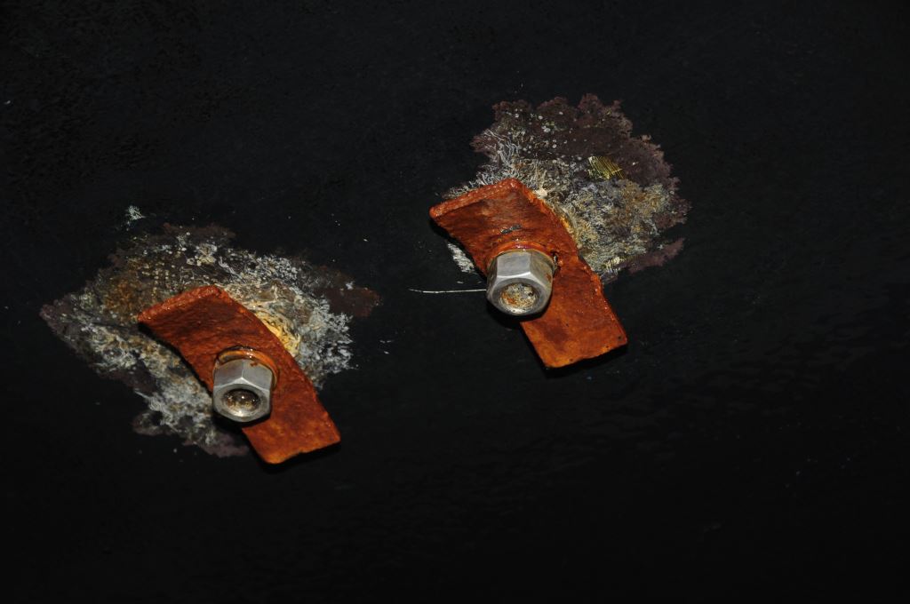
Neglecting anode replacement can be a costly error. Here, all that’s left of this anode is its embedded plates, all of its sacrificial metal is long gone.
My assessment; the stern thruster anode was doing its job (and probably not being replaced often enough), while the bow thruster anode likely wasn’t making good contact with the metal it was supposed to be protecting.
How Does Cathodic Protection Work?
The goal of sacrificial anodes is to protect submerged metals, shafts, props, logs, struts, through hulls, etc. This is achieved by driving the metals that are to be protected into a more negative voltage range, measured in one thousandths of a volt increments known as milli-volts (mV). Each metal has its own voltage range in which it is protected, typically a minimum of -200 mV beyond the metal’s resting voltage. For instance, when measured using a silver/silver chloride reference cell, the tool most commonly used for measuring protection levels, marine grade aluminum alloys’ resting voltage in seawater is about -760 mV. The ‘protected’ voltage, there is some debate among experts, you’ll often find small variations shown in different literature, the voltage it should be driven to when connected to an anode, should therefore be a minimum of -950 Mv. In my experience -900mV is more than adequate for commonly used marine aluminum alloys.
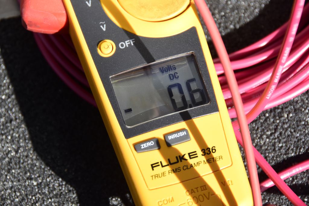
This aluminum vessel’s protection level is -600 mV, which is well below the minimum requirement.
It’s worth noting that while most metals can’t be harmed by over-protection, aluminum is an exception as it’s amphoteric, which means it is affected by both acid and base solutions; over-protection creates an alkaline or base solution around protected metals. Therefore, aluminum protection should not exceed -1100mV. Over-protection can also be harmful to the hulls of timber vessels adjacent to bonded, protected underwater metals. In a process known as delignification, the alkaline solution attacks the soft material between the grain structure.
Paint failure around bonded/protected underwater metals is often an indication of over-protection. On fiberglass vessels this is only harmful to the paint and can be mitigated with an epoxy primer.
Finally, over-protection can also cause anti-fouling paint to blister or lift adjacent to protected underwater metals, which can lead to barnacles and other growth striking on these areas; this can be mitigated by epoxy encapsulating those underwater metals.
Testing
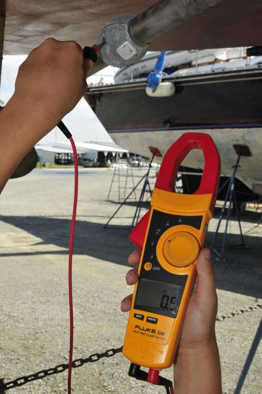
In order to carry out a reference electrode test, begin by unplugging the vessel’s shore cord; it must be unplugged, simply turning the power off is not acceptable as the ground wire within the cord remains connected to the dock’s power supply. Then, using a digital multimeter that is set to read DC volts, connect the reference electrode, typically silver/silver chloride for sea and brackish water and zinc for fresh water, to the negative lead, and the metal that is to be measured, through-hull, strut, or entire bonding system, to the meter’s positive lead.
A silver/silver chloride reference electrode. Quality varies, so choose carefully and if the price seems too good to be true, it probably is.
Then, in still water, hang the reference electrode over the side, it should not touch the hull, and take your reading. If the vessel has no bonding system, then each underwater metal must be measured by making a connection from within the hull, using extended test leads.

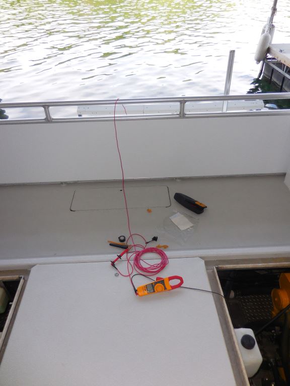
Corrosion analysis underway; testing should take place in still water, initially with shore cord unplugged, and then plugged in. If the readings change after reconnecting the shore cord, a problem exists.
If the vessel is bonded, only one reading need be taken to measure all bonded metals, however, prudence dictates all metals should be individually tested to ensure the bonding system is operating properly. For a detailed review of bonding systems, see this article. Note that the engine negative terminal, or its bus, is generally accepted as the reference point for the grounding system, and hence the bonding system.
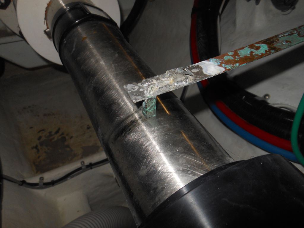
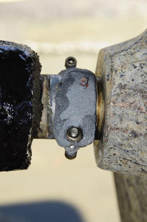
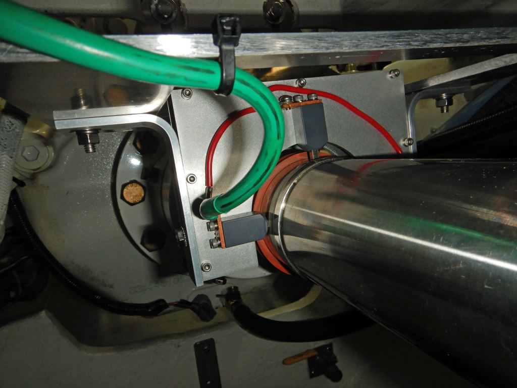
The resistance between an anode, and the metal it’s protecting, must not exceed one ohm. The one here passes the test with 0.5 ohms of resistance.
The propeller and shaft are a special case, even though they are connected to the engine via the marine gear (‘transmission’ in lubber’s parlance), and thus the bonding system, the electrical contact is poor at best because the medium is oil-filled. Common, low-cost shaft brushes can make for poor connections at best as well, the threshold for resistance between any protected metal and a sacrificial anode is a scant one ohm, so don’t count on ordinary brushes for protection.
Conventional ‘wand and carbon brush’ style shaft brushes, are incapable of meeting the sub one ohm resistance threshold, required for cathodic protection systems.
Shafts and props should have their own anodes and they should be protected and measured separately, or utilize a properly engineered brush system, one that relies on silver slip rings, which are capable of meeting the one-ohm standard.
Shafts and props are best served by their own anodes. If this is not possible, then a proper, low resistance, silver slip ring shaft brush should be used.
Repeat the testing after reconnecting the vessel’s shore power. If the readings change, the boat is not properly isolated from the shore grounding system, the vessel’s galvanic isolator, the device that is supposed to isolate the bonding system from shore power and other vessels, is not working, not wired properly or not present all together, (if there is no change, it may also indicate an open circuit somewhere in the grounding conductor’s path, a potentially dangerous scenario, check for continuity between the ground pin on the shore power cord, while unplugged from just the dock, and the AC safety ground aboard, accessed at an outlet). There also may be problems with the shore power transformer wiring, if present, and if it’s wired for isolation. For more on shore power isolation see this article.
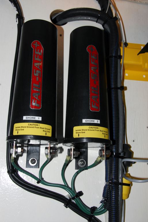
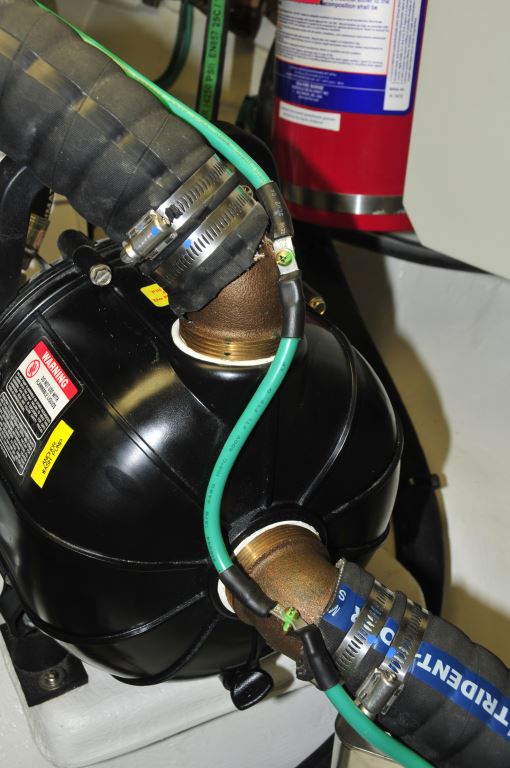
Every vessel that is equipped with shore power should utilize, at the very least, a galvanic isolator, like those shown here, if not an isolation transformer. If your bonding system is not isolated from the dock ground, your anodes could end up protecting vessels that are adjacent to yours.
When measured with a silver/silver chloride reference cell, protection ranges for seawater are as follows; aluminum -950 mV to -1100 mV; a fiberglass vessel with common underwater metals excluding aluminum -750 mV to -1100 mV (a range more conservative than that dictated by ABYC Standards); a timber hull with common underwater metals other than aluminum -550 mV to -600 mV, steel hulls -850 mV to -1100 mV.
Silver slip ring shaft brushes are capable of meeting the 1 ohm resistance requirement, which is required for cathodically protecting shafts and props with remote anodes.
Finally, as far as anodes are concerned, zinc should be used in seawater only, magnesium in fresh water only, while aluminum may be used effectively in sea, fresh or brackish water. Zinc anodes, when used in fresh or brackish water, develop a coating that causes the anode to go dormant. It can be brushed off using a non-metallic stiff bristle brush. Magnesium should never be used in sea or brackish water, as it will drive most protected metals into over-protection, which is an issue particularly for aluminum.
Zinc anodes used in fresh water develop a coating, which renders them useless. If the vessel returns to seawater, the coating can be removed with a non-metallic, stiff bristle brush.
I’m partial to aluminum anodes on hulls and underwater metals, however, I have had issues with them when used in pencil form, in internal heat exchangers. Aluminum anodes are more reactive than zinc, and as such they often develop a white surface “froth”, or aluminum hydroxide. This material does not hinder the anode’s performance; however, it can make pencil anodes difficult to remove from their heat exchanger housings.
Aluminum anodes are a win-win, they work well in sea, fresh and brackish water.
What is Protected?
Because internal metals like heat exchangers are considered to be in a ‘different body of water’ than hull anodes, the two have no effect on each other, and thus hull anodes will not protect heat exchangers, and vice versa. Furthermore, bonding internal raw water plumbing like metallic pipes, strainers and heat exchangers, will afford them no additional protection from common, every-day, galvanic corrosion, because they are too far from anodes. It may, however, provide them a measure of protection from stray current corrosion, which represents an abnormal scenario, one that occurs rapidly and is especially destructive. For a better understanding of these two types of corrosion see this article. To reiterate, cathodic protection/anodes will provide little if any protection in a stray current corrosion scenario, however, a sound bonding system can prevent or reduce damage caused by stray current, which makes it worth having, and maintaining.

Bonding otherwise isolated, fully internal raw water plumbing components, while not harmful, will afford them no protection from galvanic corrosion. Bonding may provide protection from stray current corrosion if the plumbing is submerged in bilge water.
I’m often asked, ‘what happens if I mix anode types on the hull, because I can’t get aluminum anodes for a prop, thruster (at least one thruster manufacturer has switched to aluminum anodes) or weed cutters?’ Mixing anode metals, while not ideal, is not harmful, both will provide a measure of protection proportionate to their voltage potential.
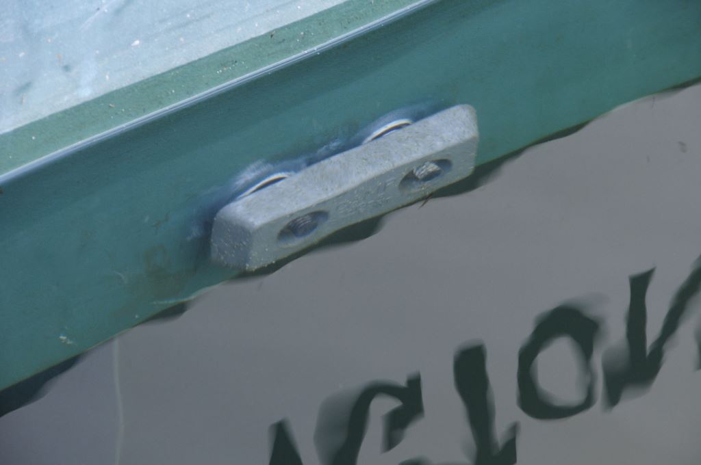
Another question that is often posed involves anode placement. While in theory any anode connected to a common bonding system will protect any bonded underwater metal, in practice, it’s best if the anode can “see”, or be within the line of sight, of the protected metal. In other words, favor positioning anodes closest to or directly contacting metals they are designed to protect. For metal hulls, distribute the anodes around the hull while increasing the density around the stern gear where the struts, props, shafts and rudders are located.
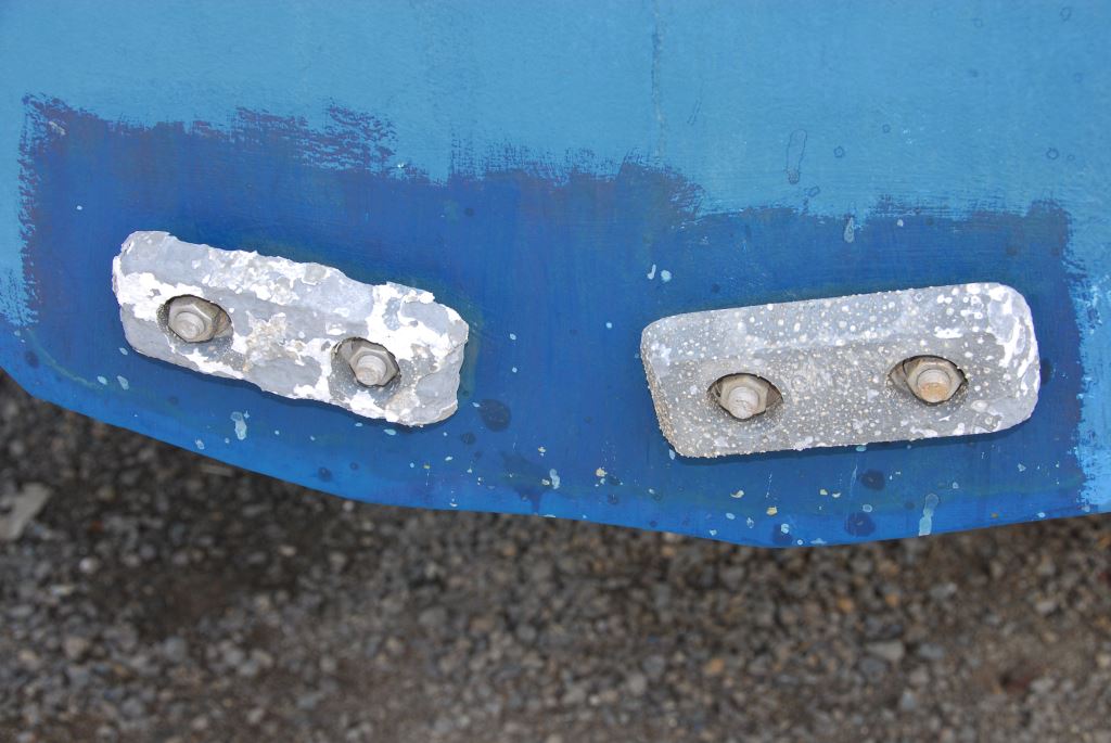
An indication of trouble; like anodes that are connected to a common bonding system, and are adjacent to each other, should decay at the same rate. If they don’t, there’s likely a high resistance issue with the one that is not diminishing.
Ultimately, when it comes to corrosion analysis, there should be no guess work whatsoever. If you are being told by a marine industry professional, or fellow boat owner, he or she believes the corrosion you are experiencing is the result of XYZ, ask them to, as one of my corrosion instructors is fond of saying, ‘follow the electrons’. In other words, explain how the corrosion is occurring by tracing the route the electrons, which travel through metals, and ions, which travel through water, are taking. If they can’t do that, then they don’t understand how corrosion works, and thus are ill-equipped to make an analysis.
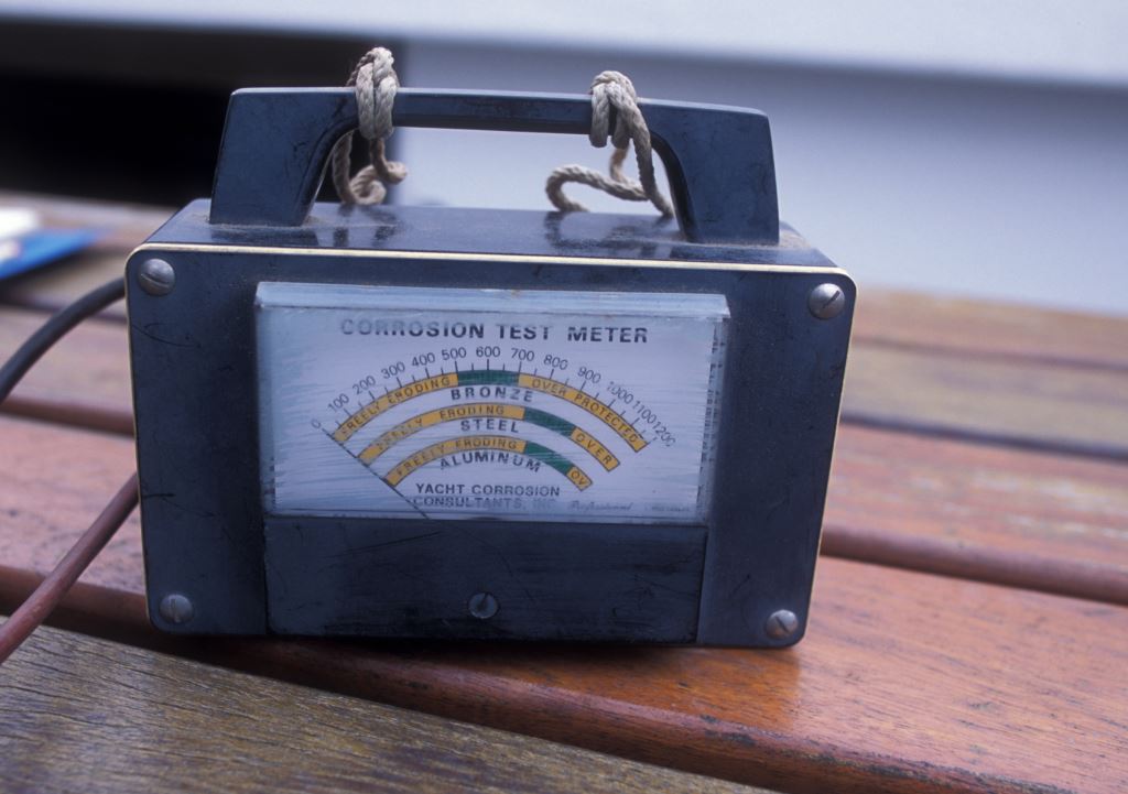
Proprietary corrosion monitors, which are simply graduated analogue ohm meters, are available and easy to use. Beware: This legacy meter shows a protected range for aluminum that is incorrect, newer models have been corrected. Make certain you confirm the protected range for your metals, rather than simply relying on a gauge face, especially if it has a lot of miles under its keel.
Whether professional or boat owner, the reference cell and multi-meter are among the most valuable tools in the corrosion analyst’s quiver. Without them, it’s impossible to know whether underwater metals are being adequately, under or over-protected.

