
From the Masthead
As I write this month’s editorial I’m in flight, returning from a series of back to back inspections and sea trials. While that sort of schedule isn’t one I’d like to repeat on a regular basis, these are both physically and mentally demanding, inspections of this sort are especially rewarding. These weren’t pre-purchase inspections, each one of these vessels have been in the possession of their owners for years. All were high quality, from some of the industry’s finest manufacturers, and all are used for long distance, inshore and offshore passage making. Why would they opt for an inspection on a vessel they already own? The goal of their masters was to ensure the vessels and their systems were seaworthy, reliable and safe. What they sought was what most mariners seek, peace of mind, but they weren’t content to sit back and hope for the best, they wanted to identify potential failures before they occurred, heading them off at the pass so to speak. While pre-purchase inspections are valuable in their own right, I relish the opportunity to spend two full days aboard a boat with an owner who knows it well, its strengths, weaknesses and eccentricities, and isn’t in the mental-overload and whirlwind of the purchase process.
Where am I going with this? My point is, you can never know your vessel too well, and it’s never too late to crawl through engineering spaces, bilges and engine rooms eyeballing each piece of gear, fastener, wire and valve. Even as a non-professional, I guarantee you’ll uncover things you otherwise wouldn’t have known about, perhaps not until a failure occurred. In every one of the above-mentioned inspections the vessel owners said, often multiple times, “I never knew that was there”, or “I always wondered what that did”. I like to say, as a cruiser, if you can move through any part of your boat and point to something and say, “I have no idea what that does”, then you have a potential problem. No part of your boat, or its myriad systems, should be mysterious. Even if you may not be able to fix it, you should know what it does and its level of criticality. If, for instance, it has something to do with steering, propulsion, or watertight integrity, one of the “mother systems” then you need to have, at the very least, a passing familiarity with its existence, repair and service needs. Most of the vessels were equipped with emergency tillers, yet, in each case their owners had never installed or tested them, and none had ever tested bilge pumps or high water alarms by controlled flooding of bilges, and they aren’t the exception. Take the time to get to know your vessel, you won’t regret it.
Bonding Systems and Corrosion Prevention
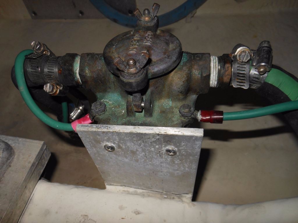
A text book example of how not to make a bonding system connection.
It’s a truism, electrical systems, and electricity in general; very likely represent the greatest mystery for most vessel owners. If you are one of these folks don’t feel badly, you are not alone. Countless skippers have shared with me, on many occasions, while aboard their boats, in e mails, telephone calls and in seminars, their self professed lack of understanding on this subject. I fully understand the mystery that surrounds this system, electricity falls into the category of faith, you simply have to believe it’s there even though you can neither see nor hear it, although, under the right, or perhaps the wrong, circumstances you most assuredly can feel it. (It’s tantamount to how I feel when dealing with accounting or legal subjects). However, you can also unknowingly suffer the effects of faulty electrical systems in ways that are not immediately obvious.
Bonding Systems
If electricity represents a mystery, then it seems that bonding and grounding and the role they play in corrosion prevention are, to paraphrase Winston Churchill, ‘a riddle wrapped in a mystery’. Many otherwise seemingly inexplicable corrosion problems are often chalked up, sometimes even by professionals, to ‘a bad ground’. Strangely enough, this is sometimes accurate; however, the folks making such proclamations aren’t sure why this is so.
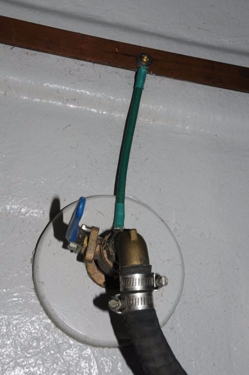
Bonding wires should be attached directly to shaft brushes, this wand style is correctly wired, rather than to the fasteners that support the wand to which they are mounted.
A few winters back, while inspecting a vessel as it rested on blocks in a local boat yard, I noticed a sharp disparity in the consumption rate of the two transom anodes (while they are commonly referred to as “zincs” the proper term is ‘anode’ as it’s possible that they may be cast from zinc, aluminum or magnesium). One had been consumed, at a rate that I would consider consistent with the vessel’s season afloat by roughly 50% (a percentage that is, incidentally the replacement threshold), the other, however, remained in a near-virgin condition. I’d seen this phenomenon before and knew something was amiss. I discussed the observation with Ryan McQueeney, president of Marine Technical Services or MTS, the squared away electrical firm located at Herrington Harbor, the yard where the vessel was stored in Maryland. He agreed to carry out a few tests to determine the cause of the uneven consumption. Hold that thought, I’ll return to that story later.
Uneven consumption of anodes is often a clear indication of a compromised bonding system.
Back to Bonding Basics
While many folks understand that it’s important and valuable to have a bonding system, few truly understand what it is or how it works. Little wonder because it can be complex and encompasses guidelines from two ABYC Standards, E-2 Cathodic Protection and E-11, AC and DC Electrical Systems, which have different goals, corrosion mitigation and electrocution/fire prevention respectively. In brief, while the terms are used interchangeably, there are differences between grounding and bonding systems and their requirements and goals and, just to keep it interesting, there’s a considerable degree of overlap. For the sake of this discussion, however, I’ll stick to corrosion mitigation and use the term ‘bonding’.
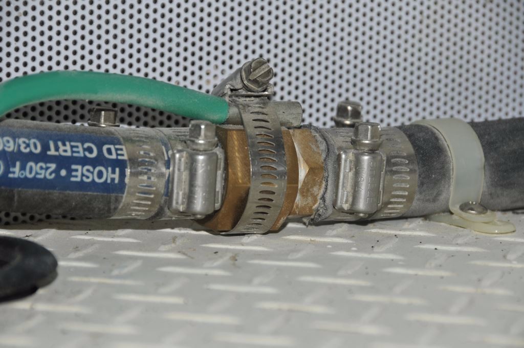
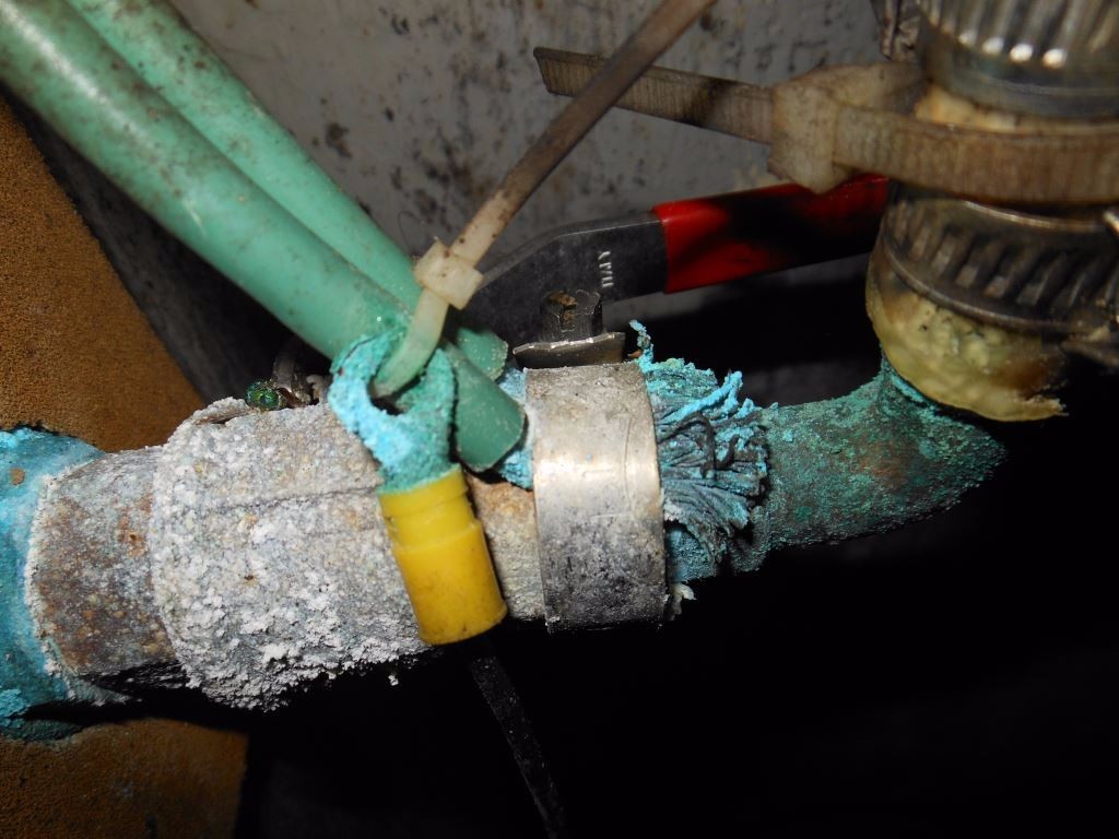
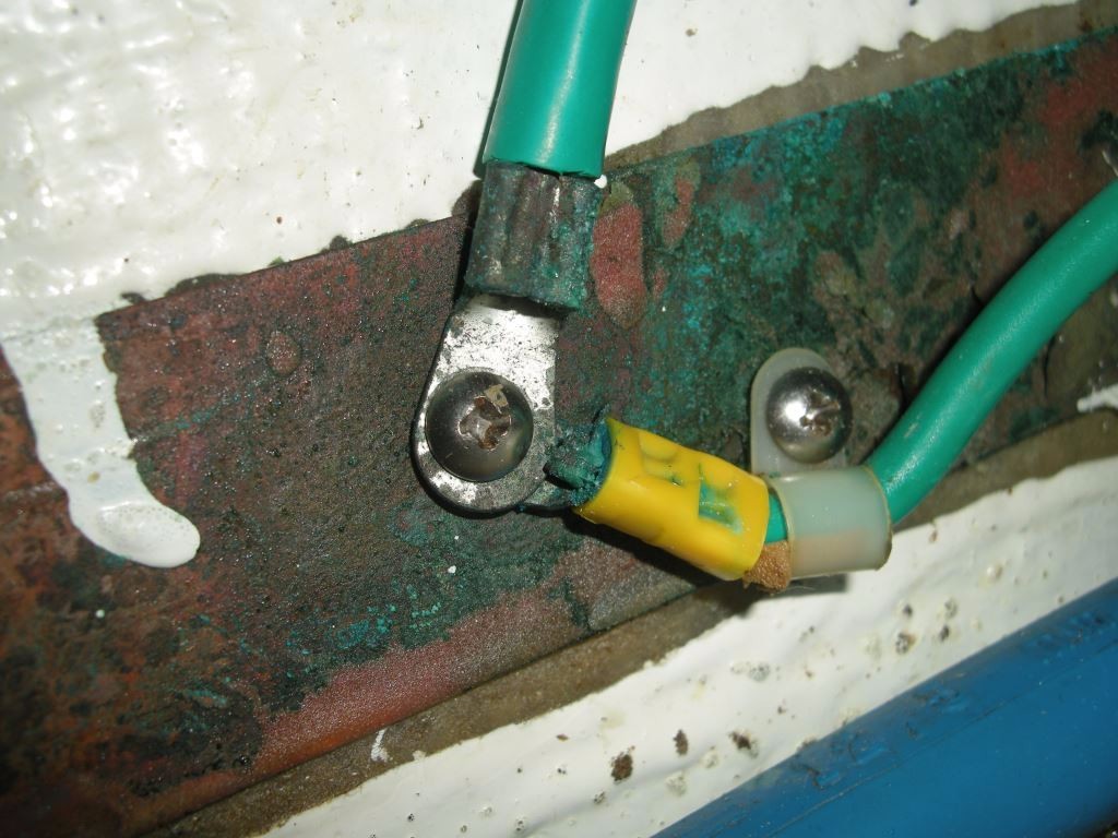
Bonding otherwise isolated metal plumbing components that carry seawater is of limited value. However, there’s no harm in doing so in spite of the fact that they are too far away from any anode to derive protection. In rare instances such bonding may be prevent stray current corrosion. Note the approved method used to make the connection, a barrel terminal has been crimped to the wire, rather than simply compressing the exposed strands under the hose clamp.
The bonding system is used to interconnect, among other things, underwater metals such as through hull fittings/seacocks, rudders and stuffing boxes (including the rudders’). Propeller shafts may be included in the system, however, because they are connected to the engine via an oil filled medium, i.e. the transmission, and because oil is an insulator, such an interconnection can be considered neither electrically sound nor reliable. Therefore, in order for propeller shafts, and propellers, to be included in the bonding system they should utilize a shaft brush, which is a device that, ideally, completes a low resistance connection with the bonding system.
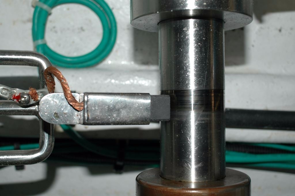
There are shaft brushes and there are shaft brushes, the one shown here relies on a spring-loaded carbon electric motor commutator brush, which is preferred. However, it still has limitations.
Shaft brushes are specifically designed to maintain contact with a rotating surface, higher quality models resemble the brush used in an electric motor’s commutator and should be made from the same material, carbon (check before you buy one, some are simply a hunk of copper alloy such as bronze or brass, which does not possess the conductivity of a proper electrical brush).
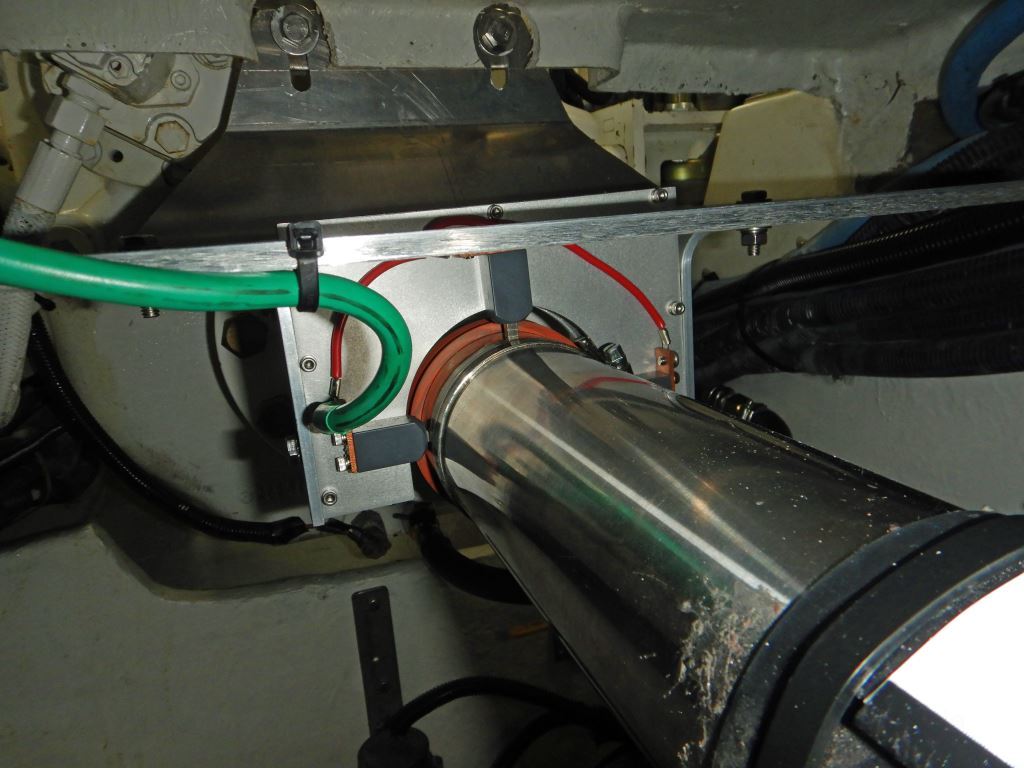
A high quality, and very effective, multi-brush, silver slip ring shaft brush assembly. If the shaft must be bonded, it must be with a very low resistance connection; this is the most reliable means of achieving that end.
Achieving the proper level of continuity, more on this in a moment, is a very tall order for an ordinary wand-type shaft brush, regardless of the material used for its contact surface, I’ve never encountered one that could do so for any length of time. Better still are shaft brushes that include multiple opposing, spring-loaded silver alloy brushes and a sterling silver shaft surface; sometimes referred to as ‘slip rings’ they are light years ahead of a common shaft brush.
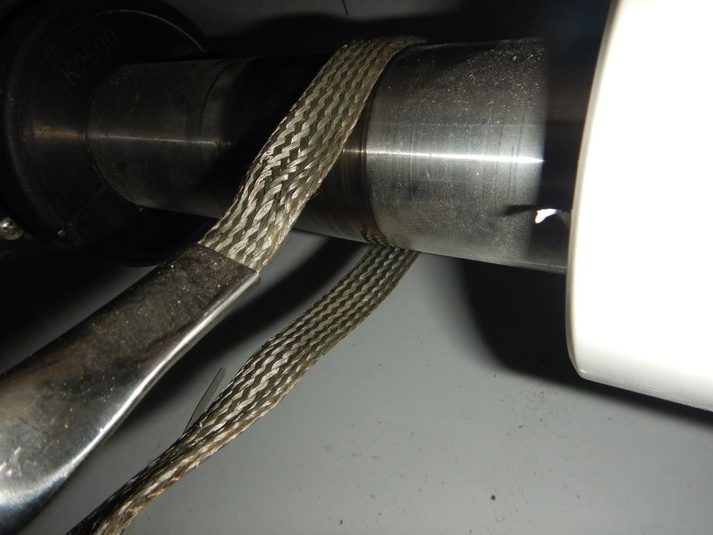
Braided shaft “brushes” of this sort are unreliable; like most other shaft brushes they too don’t achieve the sub-one-ohm requirement.
The difference in performance comes at a price, the common wand-style carbon brush or hunk of bronze is about $30, whereas a slip ring is typically several hundred dollars. While there’s no harm in using the economy version, it simply can’t be counted on to deliver reliable, continuous low resistance connection. If you are relying on anodes that are not connected directly to the shaft for shaft and prop cathodic protection, then the shaft brush’s continuity takes on a far higher level of importance.
Connecting bonded items in series, also known as “daisy chaining”, should be avoided as it adds unnecessary resistance to the circuit. Ideally, each bonded item should be connected directly to a bonding bus bar.
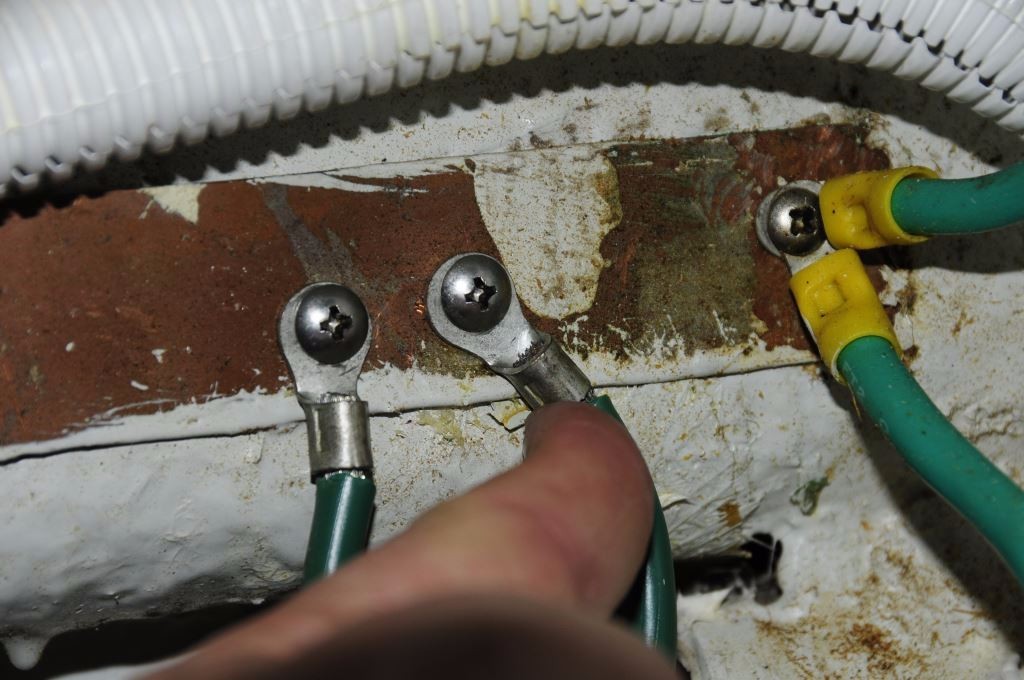
In no case should self tapping, sheet-metal or wood screws be used. If machine screws are used the strip must be thick enough to be tapped and allow a minimum of four threads of engagement. While all too common, the practice of clamping a wire’s strands to hardware using a hose clamp, should be avoided. If a clamp must be used, a barrel connector should be crimped to the wire first, or better yet, a machine screw perpendicular with and passed through a hole drilled in the hose clamp to make the connection using a standard ring terminal. Otherwise, through bolts and nuts may be used to connect a wire’s ring terminal to the strip whose thickness must be a minimum of 1/32” and the width of all strips must be no less than ½”. If, as is often the case, wiring ring terminals are connected to a bonding strip using self tapping screws which pass through the strip and into fiberglass, or worse, wood, then you can be assured of a poor connection. In almost every case when I inspect vessels whose bonding systems are wired in this manner I find universally loose connections. And, such connection methods lack ABYC compliance.
Tapping screws and thin copper strips are a poor combination, as they nearly always lead to loose, high resistance connections.
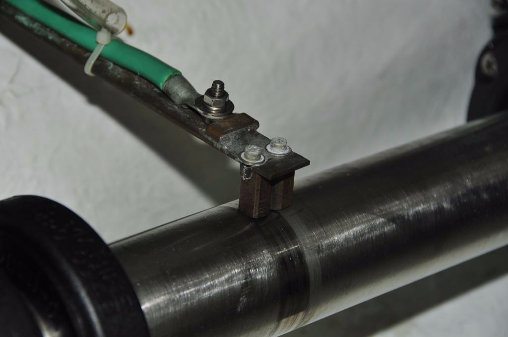
There is an alternative to the stem to stern copper bus bar/strips, one that is especially useful in after-build installations. Installing a series of purpose-made tin-plated bonding bus bars in various locations around the vessel’s machinery and bilge spaces, each of which is interconnected using marine-grade, tinned cable, will provide the installer with convenient, reliable bonding points.
The “drop” or “home run” method of bonding connection, wherein each bonded object is connected directly to a copper bus bar, is among the most reliable, while presenting the lowest resistance connections.
It’s important to note that the soundness of the connections in a bonding system will bear heavily on its effectiveness. Because the voltage and current that such a system is called on to transport are often quite low, the resistance must be equally low. Therefore, such resistance between bonded items and anodes must not exceed one ohm, a high standard for conductivity indeed, and often a tall order considering so many bonding connections are in the bilge. Bonding system connections should be periodically inspected for corrosion and fastener tension. Using a conductant paste, such as Thomas and Betts Kopr Shield, when making connections and then coating those with a corrosion inhibitor, such as CRC Heavy Duty Corrosion Inhibitor, when complete will ensure long term reliability.
The tapping screw used here, to secure two ring terminals, virtually guarantees a compromised connection. Furthermore, a few strands are visible in the terminal on the lower right, these are hard drawn copper with “few” being the operative word, there are six or seven individual “strands”, whereas a conductor of the same gauge that is approved for marine use may utilize 70 strands. Conductors of this sort are inflexible, making them prone to stress failures, and often result in poor quality connections when used with crimp terminals; needless to say they lack ABYC compliance.
The reason for interconnection of this seemingly disparate gear is twofold. One, bonding provides a low current path to ground for stray current. Stray current corrosion, which is nearly always DC in nature, is especially destructive and rapid; it can consume a propeller or turn a shaft into useless mass riddled with holes in a matter of days. Its source is typically a positive DC wire that comes into contact with bilge water; it’s often associated with bilge pump wiring. In the presence of a sound bonding system, the likelihood of severe stray current corrosion damage is reduced, although not eliminated.
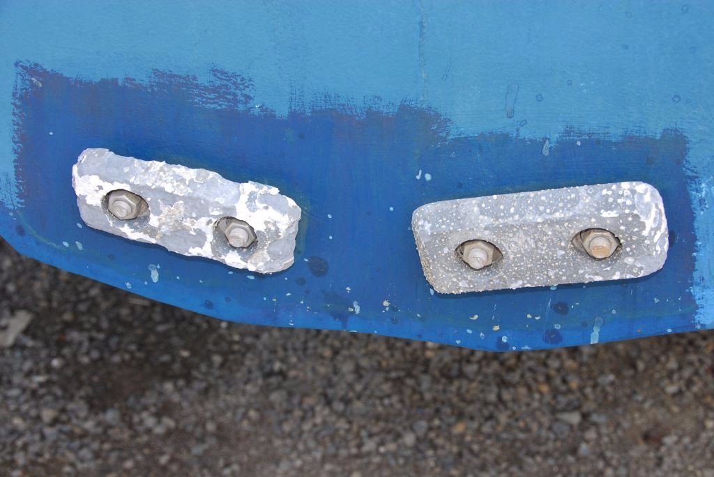
One or more anodes connected to the bonding system will provide protection for bonded underwater metals that reside in the same body of water as the anode.
Second and relevant in the aforementioned vessel’s case, when the bonding system is connected to a sacrificial anode as it always should be (the anodes used aboard this vessel are aluminum), then that anode will then afford protection to all metals that are interconnected and immersed in the same body of water. Such an arrangement makes it considerably easier for a vessel operator to protect multiple metals by maintaining just a few anodes. If the metals are not in the same body of water, i.e. the engine and generator contain seawater; however, for all intents and purposes it is not the same water as that in which the vessel floats, then hull anodes will do nothing to prevent corrosion within the engine and generator, even if they are connected to the bonding system. It is for this reason that engines and generators are equipped with their own sacrificial anodes.
The rest of the story…
Using a multimeter, the resistance between the pristine anode and the bonding system was tested. That analysis yielded the answer to the anode’s unusually long life; the connection between its mounding stud and the bonding system wire ring terminal was abnormally high, well above the one ohm threshold. That was enough to prevent it from offering protection, and being depleted in the process. Once the connection was cleaned, and brought back into compliance, the anode was back on line and doing its job.
Next month I’ll talk more about anode selection, installation and maintenance along with galvanic isolators and why they are so important. I’ll also share with you the results of the bonding system inspection.
Follow this link for Part II of this article.

