
Text and photos © 2021 Steve D’Antonio Marine Consulting, Inc.
Photo Essay: Wire Design
It’s a question that occasionally comes up among boat buyers or forum dwellers, one relating to the type of wiring used aboard a particular vessel. One of the more common misconceptions holds that the wiring used for small craft and yachts must be tinned.
Tinned marine grade wiring is made up of common, stranded copper conductors, each one of which is coated or plated with tin. Tin is naturally corrosion resistant, and because it encapsulates the copper it prevents it from oxidizing or developing the familiar green verdigris, which in turn can lead to high resistance, heat generation, arcing and even fire.
However, the American Boat and Yacht Council Standards (more on what ABYC is, and is not, here), the voluntary guide that is recognized and used by much of the marine industry, includes no such provision for tinned wiring; while it’s desirable, it’s use is not mandatory for ABYC compliance. Having said that, I can’t imagine building or repairing a vessel today using anything but tinned, marine-grade wiring; it will improve reliability and for the cost it offers good value for the money.
Rather than asking whether or not it is tinned, perhaps the more important question should be, what type of conductor is used. In other words, how fine is the stranding? Strand thickness and quantity has a direct effect on a wire’s flexibility. Solid wire, like that used ashore, is relatively stiff, bend it enough times in the same place and it will break. Ashore that’s not an issue as wires usually aren’t flexed, but afloat it’s another story; it’s why solid wire is prohibited where ABYC compliance is concerned.
ABYC Guideline on Stranding
Type 1 – Solid conductor and stranding less than that indicated under Type 2 shall not be used.
Type 2 – Conductors with at least Type 2 stranding shall be used for general purpose boat wiring.
Type 3 – Conductors with Type 3 stranding shall be used for any wiring where frequent flexing is involved in normal use.
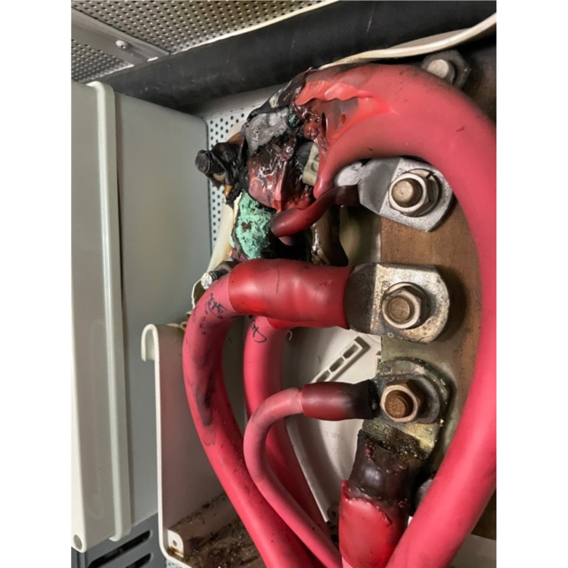
As an example, referring to the guideline above, a Type 2, #12 (the conductors shown in the accompanying image are #12) stranded conductor, should have a minimum of 19 individual strands, while a Type 3, #12 conductor should have 65 individual strands. The conductors shown here, with their coarse (just seven individual strands) design, are intended for industrial, machine and shore-side applications. Under no circumstances should conductors of this sort be used aboard a seagoing vessel. While ABYC Standards allow for the use of Type 2 stranded wiring in most applications, where frequent flexing is not anticipated, my preference is for the use of Type 3 stranding throughout the vessel.
Ask Steve
Steve,
I was not sure what email address so I tried what I could find.
I have a 2001 Great Harbour trawler that was built with fuel tanks that are “glassed” in between the stringers. From construction photos, I believe once the wooden stringers where attached to the solid fiberglass hull, the stringers were fiber glassed into place, plywood was put between the stringers to form a box, and again fiber glassed into place. It was then gel coated I believe, before a fiberglass encapsulated top was mounted to complete the tank.
At the aft of starboard fuel tank, on the floor of the engine room, I am finding an ounce or so of diesel fuel. If I clean it up, the fuel comes back in a few days. I am thinking the diesel fuel is leaking from inside the tank either into the stringer or hull fiberglass and then onto the deck. I could drill a few small holes in the stringer to see if I find more fuel. I would rather not be drilling holes in the floor of the engine room (hull).
I have asked several yards and their solution was to pump the tank empty and pressurize the tank to find a leak with soap bubbles or put a bladder in the tank. My concern is that I have a stringer with diesel in the wood or diesel in a void in the fiberglass mat or some place.
What should I be worried about? Is there a resin or epoxy that resists diesel and could solve the leak?
Regards,
Henry J. Dennig
Henry:
Fiberglass is one of the most desirable materials one can select for the construction of diesel fuel tanks. If done right, such tanks will last the life of the vessel.
The yards with whom you’ve consulted have given you sound advice as far as leak detection is concerned, the first step would be a (low, not more than 3 psi) pressure test to try to find the source. I am no fan of bladders, so that’s not an option for the repair in my view.
The preferred, and most secure method of building a fiberglass fuel tank is to shape it to fit, yet fabricate it separately from, the vessel, and then tab (fiberglass) it in place. Integral tanks, those that utilize the vessel’s structure for some portion of their sides, are on the other hand somewhat more risky. If the vessel flexes significantly, during a grounding for instance, when hauling, or if not blocked properly, the tank’s tabbing could separate from the hull, leading to leaks.
Here’s what ABYC has to say about integral tanks…
“Tanks may be integral with the hull If cored hull construction is used where the tank is integral with the hull, the core shall not deteriorate from exposure to diesel fuel, and commonly used additives, and shall not permit fuel to migrate.”
I don’t know which of the two systems Great Harbor used, isolated or integral. In the former case leaks are, while not impossible, very rare. Integral tanks are more prone to issue for the reasons mentioned.
If diesel fuel has penetrated the core I’m afraid there’s no easy solution, however, my advice would be to not spend time worrying about that until you have confirmation, this may be a simple fiberglass tabbing issue.
With some caveats, there are both epoxy and vinyl ester resins, which are suitable for use with diesel fuel. When the leak is found, the most important task will involve thoroughly cleaning the area, making certain all fuel residue has been removed. This will likely involve grinding/sanding as well as chemical cleaning. Once that’s complete the leaking area can be patched or re-tabbed depending upon the size of the affected area. Once repaired, the tank should once again be pressure tested.
Dear Steve,
Thank you for the great work you do with your website, “eMagazine” and magazine articles to provide us boat owners with knowledge and inspiration to do the right things to keep our vessels and ourselves safely afloat.
I understand the reasons for “properly/adequately loading” a diesel engine, and with propulsion engines, it’s a simple matter of setting your rpm’s. With a diesel generator, it’s not so simple. I have a Northern Lights 5kw generator, Model M673L2.3, that my manual says runs at 1800 rpm, but how can I determine if it is properly loaded? My AC ammeter shows me the load when I switch on water heaters, air conditioners, microwave, etc., but it does not indicate the load from my battery charger. My DC ammeter will give me the net amps I am putting into my batteries, but again, no indication of what that means in terms of load on the generator. My inverter/charger is a Mastervolt Mass Combi Model 12/4000 (120V & 230V). My vessel is a 2008 Antares 44 sailing catamaran, the last one built by PDQ in Canada.
Sincerely,
Alan Bradley
Alan:
Your AC ammeter should provide you with everything you need to determine the load on your genset. A 5 kW genset will produce about 41 amps at 120 volts. Therefore, if you are drawing 20 amps (or 2400 Watts), you are, roughly speaking, loading the genset to 50%. You can use this Ohm’s Law calculator to Wattage, current or voltage of you have either of the two.
I am puzzled however, when you say that the AC ammeter does not register the load from the battery charger. That’s curious and on the face of it appears incorrect. If the battery charger is wired before the shunt for the AC ammeter, that would explain this peculiarity, however, I can think of no reason why this would be the case.
Using some simple arithmetic you can calculate the charger’s load by simply converting the current entering the batteries to Watts, multiply the volts by the amps to arrive at this figure, and then add that to the genset’s load.
Finally, you might find this article of interest http://www.proboat.com/2015/02/why-you-shouldn-t-go-easy-on-a-diesel/
Hi Steve,
I have found it necessary to remove a portion of my Kadey Krogen’s SS rub-rail for repair, I have a little bump in a steel sided lock.
What sealant/adhesive would you recommend to reset the rail? It’s mechanically fastened every 6 inches and the old sealant was easy to release and very elastic. I appreciate any information you could provide, I was leaning towards 4000uv, but I’m uncertain.
Thank you in advance,
Jeff Goode
Jeff:
The most effective way to select bedding/ adhesive/ sealant is to first determine its goals; what do you want it to do, and equally as important, what do you want it not to do.
Hopefully, the fasteners that secure the “iron”, the name given to the stainless chafe guard that is fastened to the fiberglass protrusion called a rub strake, aren’t screwed directly into timber core of any sort. If the core of the rub strake is timber (some are mahogany), it should be “closed out” by “reefing and backfilling”, essentially over-drilling every hole, back-filling with thickened epoxy and re-drilling (see link below for more on this). This approach prevents water from accessing and saturating the core when (not if) the bedding fails. Under no circumstances should bedding/sealant ever be relied upon to prevent water entry into core, especially timber core. Still, using the liberal application of bedding approach, to seal each fastener, doesn’t hurt as it will prevent crevice corrosion of the fastener shanks and threads.
Assuming, on the other hand, the rub strake is solid, or filled with closed cell high density core, then water entry through fastener holes remains undesirable but is less of an issue. The goal of bedding the iron is to prevent water from migrating, and remaining, between the iron and rub strake. If it is allowed to do so, the result will be brown staining caused by crevice corrosion. That gap must, therefore, be completely filled with sealant, sometimes called bedding, ensuring ample ‘squeeze-out’ during the installation process. While you could use an adhesive sealant, such as 3M 4200, it’s not necessary. Furthermore, in my experience, polyurethane adhesive sealants such as 3M 4200 and 5200, often release from stainless steel substrates over time, allowing water to enter the gap. Polysulfide bedding compound, on the other hand, is less prone to this phenomenon. Additionally, as a non-adhesive, it remains pliable making removal in the future much easier, and, unlike polyurethane it is impervious to fuel, and most chemicals. While 3M discontinued its 101 series of polysulfide bedding compound several years ago, it remains available from other suppliers including Lifecaulk.
Preparation of the surfaces that are to be bedded, especially the stainless steel “iron”, is critical, be sure to follow the instructions provided in the link below.
Surface prep and fastener installation: http://www.cruisingworld.com/how-to/maintenance/clean-before-you-install
Core closeout, reefing and backfilling: https://stevedmarineconsulting.com/wp-content/uploads/2021/01/TaskSheet189-Closeouts-05.pdf
Stainless steel and crevice corrosion: https://stevedmarineconsulting.com/stainless-steel-miracle-metal/
Caulk: https://stevedmarineconsulting.com/caulk-and-sealant-selection-and-use/
Brown stains on gelcoat: http://www.cruisingworld.com/how/go-after-those-rust-stains
Hi Steve,
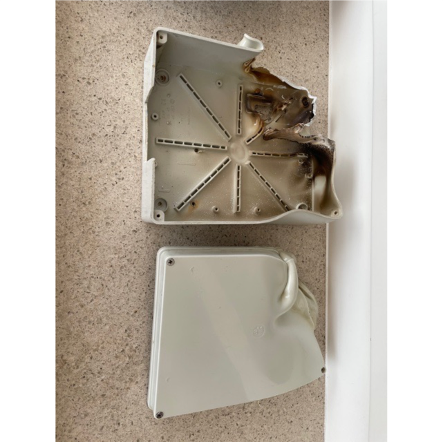
In your Pre-Purchase Inspection Report on my boat two years ago you made the following observation: “Junction box above batteries, a loose connection is arcing and has caused heat damage. A. ABYC T:1. 677-681.” The dealer from whom I purchased the vessel has electricians, carpenters, etc. for commissioning and maintaining customers’ boats, so I gave them an initial list including this item to be done before I used the boat. They checked this item off as complete. Shame on me I never opened the junction box to check.
So last week the main engine big alternator quit charging the house batteries when underway. I did some basic troubleshooting at the alternator and regulator and could not find an issue. When the electrician at the Hinckley yard here checked it out, he came up and said “Your alternator is working fine but your problem could be the melted junction box on the aft bulkhead of the engine room.”
So, all is fixed now, but I have learned the hard way to inspect work I thought was done. I suppose I’m lucky there wasn’t a fire.
John:
I’m relieved this did not progress to the catastrophe stage; you are very fortunate.
A number of years ago I worked for a man who was fond of saying, “Inspect what you expect”. It stayed with me.

