
Photo Essay: The Perils of Double Grounding
It is ubiquitous, various disparate onboard equipment, to which green bonding wires are attached. While not necessarily providing any benefit against corrosion, this is generally harmless. There are, however, exceptions, particularly in the case of AC electrical equipment.
Virtually all AC electrical equipment, which utilizes a metallic case or enclosure, includes an AC safety ground as part of the equipment’s integral wiring, this green wire is, and must be, run together with the hot (also called “ungrounded”) and neutral conductors. If a fault develops, and a hot conductor makes contact with the case or enclosure, the green safety grounding wire safely conveys that current back to the source, where it should trip a circuit breaker, thereby clearing the fault and de-energizing the circuit, rendering it safe. Without that intact safety grounding wire, the metallic case or enclosure would remain energized. If a person then came along and touched it, and something that was grounded, like an engine block, seacock, or other bonded/grounded component, he or she would complete the return path, and be shocked or electrocuted.
In the accompanying image, an AWG #8 green bonding wire can be seen attached to this HVAC raw water pump motor casing. This is an exceptionally common sight, and on the face of it, it’s easy to assume that grounding a component that has both AC power and seawater present, for both electrocution and corrosion prevention, is a good idea. However, by virtue of this motor’s AC power supply wiring, it is already grounded via that power supply’s AC safety ground, and thus the visible green wire represents a double ground of sorts, and a parallel path between the AC safety ground and bonding systems; and parallel paths between these systems are both prohibited by ABYC standards, and potentially problematic.
It’s safe to assume that if a manufacturer does not include a dedicated, and marked bonding stud on their equipment, it should not be supplementally grounded. In this case, the correct approach would be to disconnect the added bonding wire, then confirm the continuity of the case with the AC safety ground system.
Ask Steve
Hi Steve,
After reading Charging Challenges in Cruising World, we are convinced we should do something with our present setup.
Our 24V house bank is charged with an extra alternator, but it needs an external regulator. Can you give us any advice? 800 Ah AGM house bank, the present regulator type 8RG3088.
The alternator is a BLD3088 24V 140A Prestolite Leece Neville.
Thanks!
Peter Buijs
Peter:
External regulation is hard on alternators, it generates a lot of heat, so it’s important to make certain the one you are using is designed for the task. Provided the alternator is designed to be externally regulated (I’m partial to Prestolite Leece Neville heavy duty alternators, but I’m not familiar with this specific model), you should look for a regulator that include features like easy programming, both battery and alternator temperature compensation, and self-diagnostics to name a few. You can read more about this selection process here.
Proper installation/wiring and programming of the regulator is critical, and make certain your alternator has sufficient ventilation, and the fan isn’t obstructed by shields or guards. Overheating is the primary cause of early failures in high output alternators.
Hello Steve,
Thank you for your great articles, they impart so much knowledge.
This query involves small Universal diesels on sailboats – particularly that the temp gauge sender and hi-temp switch can be problematic being located on the thermostat cap. Poor contact through to the block (cap gasket, sender/switch threads, cap bolt corrosion) can cause temp gauge inaccuracy.
I have a bonding wire that clamps around the body of the sender to make a good ground (see photo). Is that wise/acceptable? And it grounds to the nearest good location (the alt B- or a nearby neg buss for the engine panel harness and other negs.)
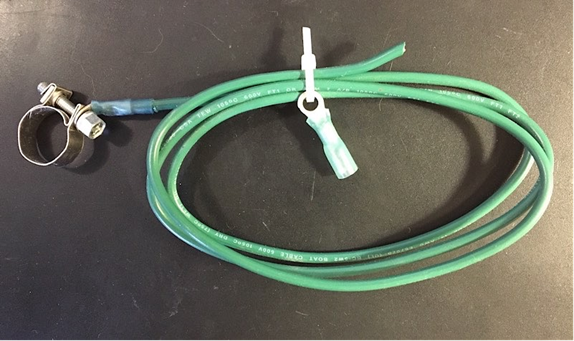
Is this ok? I’m rethinking that “just in case” it should be on an engine bolt or stud, possibly a stud on the water flange? But then it’s subject to the same corrosion issues as is the thermostat cap bolts.
In a quandary,
Ken Kloeber PE
P.S. The alt/starter are not of the isolated neg type.
Ken:
You can augment the sender’s ground, however, the wire from the sender must not leave the engine, i.e. do not connect it to the battery or vessel negative bus, doing so could enable it to attempt to carry a portion of cranking or charging current. If the block’s primary DC negative cable were to be disconnected or otherwise compromised, that small grounding wire could attempt to carry hundreds of cranking amps, which would cause it to quickly overheat and potentially cause a fire. It should be connected to a block fastener, over a clean, unpainted surface. This will not lead to any unusual corrosion issues.
Generally, and for ABYC compliance, engines that do not utilize an insulated ground starter and alternator, i.e., the engine block is a current carrying part of the DC negative circuit, should not be part of the DC grounding (similar to bonding except we reserve that word for parts that are immersed in seawater) system, their DC negative cable is all that’s needed. If the engine does use isolated ground components, the block should have a supplemental grounding wire, one that is capable of carrying full fault current, i.e. it must have the same ampacity as the largest positive cable, which is usually the one that supplies power to the starter (it can be one size smaller than that cable).
More on undersized grounding here.
Dear Steve,
My boat has two battery banks, each bank is two 6-volt batteries wired in series making each bank 12 volts. The two banks are controlled by a selector switch… Off, 1, 2 or both.
I want to install a battery monitor on each bank to monitor them independently. Assuming the shunts are wired correctly on each bank, does it matter that the two banks share the same common ground on the engine?
Will I be able to achieve what I am trying to do?
Thank you very much for your time.
James DeBrum
James:
As long as the shunts are installed in the negative wires at each battery bank, after 12 volts is created, but before any other loads are connected, or paralleling occurs, the monitor will accurately read power consumption/use and charge to the battery banks individually. However, if cranking current is being pulled through this shunt, because one of these batteries is used for starting, make certain the shunt(s) is rated for that load. If it is not, when you crank the engine you could overload it, which could damage and it and lead to an open DC negative circuit, which in turn means no power would be available from the bank.

