
Text and photos copyright © SDMC, Inc. 2016
Ask Steve: May 2015
Good day Steve!
I have a question that your readers and I would benefit from, your knowledge and perspective about replacing my current A/C compressor, and keeping the two (2) existing OEM air handlers in the aft and v- berth cabins, versus upgrading the complete A/C system to all new compressor and two new air handlers.
Boat facts: I have a 1980 Grand Banks 42 Classic with original 3 rotary knob Cruisair split system air conditioning system. The 12K BTU compressor uses R22 and is in the engine room providing A/C to the split system two air handlers mounted in the closets of the aft and v-berth cabins.
I would like/need to replace the compressor which has been showing its age. My question to you is the pros and cons of the options:
#1. Replacing the OEM Cruisair compressor only with a new dry compressor unit, continue to use R22 refrigerant and continuing to use the two (2) existing OEM air handlers which have shown no problems, which would minimize immediate equipment costs and installation expense versus
#2. Replacing both the OEM Cruisair compressor and the two (2) existing OEM air handlers with new units to get away from R22, to use newer refrigerant versus…
#3. Replacing the current OEM split system compressor and the two air handlers with two (2) individual stand-alone A/C units to be located in the aft and v-berth cabins each with their own controls
What are your recommendations?
Thanks in advance,
Patrick Kirschling
Patrick:
I’m afraid there’s no clear or easy answer in a case like this. In short, while I appreciate thriftiness as much as anyone, and I hate to throw away gear that is working, I’d be reluctant to marry new equipment, and the cost of installing it, to 30+ year old air handlers, regardless of their seemingly good condition, for whom spares and service are scarce, and getting scarcer. Additionally, any warranty issues could get murky if new and old gear are mixed.
Either way, split systems can be problematic where after-market refits are concerned, whether it’s a complete system or piecemeal parts replacements, they require experienced folks who know how to reliably solder refrigeration plumbing, vacuum-down the system and then charge it properly with refrigerant.
While there’s more expense involved, my inclination would be to say, ‘you got your money’s worth out of this system, time to retire it in its entirety’. Make certain the folks installing agree to do so in complete compliance with Cruisair’s installation instructions, including and especially the evacuation requirements prior to charging split systems, if you are unable to use self-contained units, and raw water supply design and materials. The use of PVC should be avoided for raw water plumbing, stick with bronze or glass reinforced nylon, and only hose specifically rated for marine HVAC raw water (or SAE J2006R rated hose) should be used.
Steve,
Your article re: fuel tanks is excellent. This is a biggie issue you properly highlight.
Please share your thoughts on 2 subjects;
- All liquid tanks -water, fuel, holding, etc. –isn’t your structural assessment valid for all tanks?
- Many tanks that were cut-open show internal failure that actually initiated the exterior leak identification. From a technical perspective; fuel tanks usually have some water in the bottom. Fuel tanks with electrical gauges are grounded by the fasteners between the sending unit and the tank (even though the sending unit is gasket-insulated from the tank). They also may be intentionally electrically grounded. Therefore, the tank and the water is in reality a battery-and here comes the internal failure.
I just viewed a 54 year old Linwall-built wood boat with original black iron fuel tanks with “0” issues, as confirmed by the inspecting surveyor. The one redeeming factor–no fuel gauge or tank grounding to the electrical system or the zincs; just a mechanical sight glass. Compare this with the rampant black iron fuel tanks that are replaced regularly on the Grand Banks at 18-25 yr. intervals (all with electrical grounding and electrical gauges.).
Thank you in advance for your thoughts.
Steve Kraus
Steve:
Tanks, particularly fuel but others as well, are a sensitive subject to be sure, and with good reason, failures are nearly always costly, inconvenient and in some cases dangerous.
Indeed, structural and support issues pertain to water, gray and black tanks as much as those that contain fuel. Issues with fuel tanks are often more acute and, of course, more troubling. All tanks should be well supported, either on a continuous shelf, or they should be designed and constructed to be self-supporting.
As far as tank corrosion, and its relationship to bonding or grounding is concerned, this is a very good question, it illustrates a common misconception regarding bonding. The severely rusted black iron or steel tanks shown in the article would have failed regardless of whether or not they were bonded. In order for tank corrosion to be induced by bonding, several criteria would need be met. The tank would need to be bonded to a more noble metal, copper or bronze for instance, and both metals would need to be immersed in the same electrolyte, i.e. the same body of water. This phenomenon is clearly exhibited and used to a vessel’s advantage, and periodically its disadvantage, via the bonding of underwater metals and their collective attachment to an anode, zinc or aluminum. The anode protects all of the metals to which it is connected because they all reside in the water in which the vessel floats. This is an essential aspect of galvanic corrosion, all of the involved metals must be in the same body of water. However, that same anode is incapable of preventing corrosion within an engine or generator raw water cooling system, and vice versa (they are a different body of water), which is why the anodes within an engine aren’t quickly consumed in an attempt to protect the propeller, shaft, strut etc. Having said this, if the tank was standing in bilge water, along with a bronze seacock, and the two were bonded, the tank would be anodic, and its corrosion rate would be accelerated as it sacrificed itself to protect the seacock, in much the same way a zinc anode sacrifices itself to protect a propeller.
The water inside a fuel tank has no bearing on this process per se, regardless of bonding, once again. However, such water is capable of wreaking havoc on its own, creating rust as well as fostering biological life, the byproduct of which is corrosive hydrogen sulfide, which would further accelerate the corrosion process.
As an aside, ABYC guidelines mandate that all metallic fuel tanks be bonded. That bonding wire is the only one aboard that is allowed to routinely current, albeit small, from the tank sender, an additional ground wire is prohibited as a potential between the two can be established (which in turn is why no equipment should be double grounded, but that’s a subject for another letter).
The fact that the old black iron tanks you encountered were not rusted had nothing to do with bonding. They may have been thicker, made of a more corrosion resistant alloy (one with a high nickel content for instance), more thoroughly coated or coated with a more corrosion resistant paint, they may have been better maintained, lived in a different, drier climate, or they may have been installed in a manner that promoted long life, with good drainage and sloped horizontal panels.
Hi Steve,
Excellent column as usual.
Last week the car wouldn’t start, dead battery, 5 years old. I got out our Napa battery charger and after 4 hours still the same condition. We called AAA who came out and told us the battery was dead.
The mechanic told us that since the battery was dead, not low, the charger wouldn’t charge it. This is because newer style chargers have a protector inside that prohibit the charger from sending current into a dead battery for safety reasons.
True, or wives tale? This might make a good column for boating batteries.
Thanks,
Paul and Marlene
Paul:
After five years it’s certainly possible the battery was dead and wouldn’t take a charge.
Is it the type of battery that allows you to check the electrolyte? Those are rarer now, however, these often need water every year or so, if it went dry then a charger would have little effect. While you were charging it was the charger indicating output on its amp meter (if it had one)? If so, then no safeguard was in place. Still, it doesn’t mean the battery could accept a charge, if the plates were heavily sulfated it would generate heat but not necessarily take a charge.
Typically, many modern chargers won’t charge an internally shorted battery, as a safety measure, and they won’t charge a battery that is completely flat, i.e. 0-3 volts. If your battery was in either state, then no amount of charging would have an effect.
You’re right, it’s time to revisit routine battery maintenance and jump starting, look for that column soon.
Steve:
Two years ago I wrote to you asking for suggestions concerning a Yanmar 110 that stalled at slow speeds.
The boat was a Ranger Tug 25 with only 200 hours on it.
The engine ran great all day long, but on hot days or after long runs as I slowed down to enter a dock the engine would quit.
This caused several near disasters and one real disaster.
It ran great on cool days or short runs.
The temperature remained an ideal 170 degrees.
The short term solution was to rev it up in neutral and cram it into gear, and it ran great.
You said write if you ever figure it out.
After 5 diesel experts took a crack at it and after about $2000 in bills we had no solution. Mack Boring had been contacted and made several suggestions for the mechanics to try, but to no avail. We were getting pretty discouraged.
Then one day, after tying up at a marina in Kingston, Ont. I got into small talk to the next slip captain who just happened to be an auto mechanic and who had also the exact same symptoms on his gas powered vessel. He said “it is not your engine it is the throttle cables. They overheat and stretch”.
We took an 8mm and a 10mm wrench and increased the idle speed to 850 and lo and behold the problem was fixed in less than 5 minutes. Since then we have had repeat this step occasionally, but for the most part the long term problem was fixed. The idle was falling below 600 causing the engine to stall out.
I made a new friend and it only cost me one beer.
Do not know if this is a common problem or not, but I thought I would pass it along.
Love your great articles and common sense approach to safe boating.
Bert Sampson
Dear Bob:
Thanks for sharing the update. While it’s not a common problem, I have encountered it on one previous occasion, which was also rectified with increased idle speed. Thus, I’m somewhat embarrassed I didn’t think of it. Ever since my experience with this scenario, I’ve tested every vessel I sea trial for this sort of stalling. Perhaps other readers will be saved the grief you experienced after reading this tale. There is, however, fly in this ointment. The throttle cable adjustment and length should have no effect on idle speed. Idle speed is, or should be, purely a function of the adjustment of the throttle lever stop on the engine’s fuel injection pump. If your throttle cable or lever mechanism is acting as the idle adjustment, it’s not set up properly. So while the solution of increase idle speed if valid, had the system been installed in accordance with Yanmar’s installation instructions, and had one of the parade of mechanics checked this, the problem never would have occurred as cable length would have no effect on idle speed.
Photo Essay: Ring Terminal Order
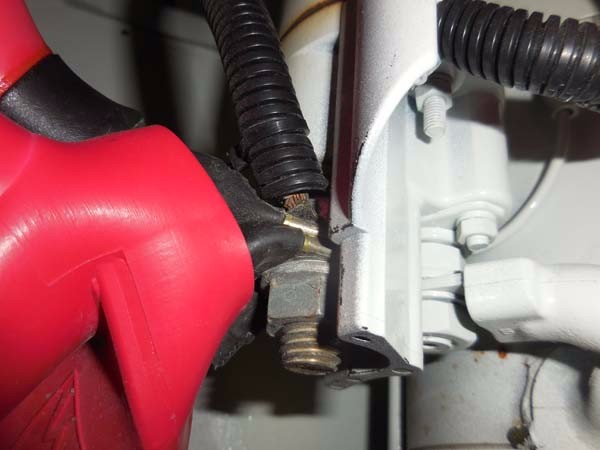
In last week’s edition of the Marine Systems Excellence eMagazine, I covered the subject of wire terminal crimping. I emphasized, among other things, the importance of selecting high quality components and tools, and then using them to ensure reliable, long lasting installations.
Beyond that, however, after the terminal is attached to the wire, there are additional nuances involved in achieving a reliable, and safe electrical terminal installation. Installing a ring terminal, or multiple terminals, using screw or stud fasteners, requires that the installer understand guidelines established by the American Boat and Yacht Council (ABYC), which specifically cover this process; the first, and perhaps most important, calls for the inside diameter of the ring terminal to match the outside diameter of the fastener’s shank. While that may appear self-evident, it’s an all too often violated standard.
Yet another frequently violated standard relates to the ampacity or current-carrying ability of the terminals when stacked. When more than one ring terminal is installed on a stud, the maximum allowable is four, the largest and therefore highest ampacity terminal must be installed first, with successively smaller, lower ampacity terminals being placed afterward. Failure to follow this protocol can lead to high resistance, which in turn leads to lower voltage supplied to the component, and heat generation.
In the example shown here, ring terminals on a starter’s positive post are installed in the incorrect order, the smallest one has been installed first. This is extremely common, particularly where starters are concerned, as the engine ships from the manufacturer with one or two small ring terminals already installed on this stud, often for instrumentation, ignition and pre-heating systems. The boat builder then installs the heavy primary cable onto this stud without first removing these smaller ring terminals, establishing the potential for poor starter performance, and terminal/stud overheating.
Check the positive (and negative if it’s an isolated ground unit) starter post on your starter for this insidious problem.

