
From the Masthead
Just Say No to Varnished Steps and Treads
A few years ago, I wrote an editorial for Professional BoatBuilder magazine entitled, “No More Mr. No Shoes”, in which, contrary to convention, I advocated for those in the marine industry, not going shoeless. In what other industry, I argued, would professionals be expected to work with, and on, machinery, while barefoot? And yet, I was recently aboard a 60-foot vessel while under construction, and every one of the craftsmen and women aboard were shoeless, while they installed everything from air handlers to engines.
Related to this pet peeve is one that involves step and ladder treads. Once again I ask, under what other circumstances would an industry go out of its way to make a surface, on which one walks, more slippery, in an environment that is inherently and unpredictably unstable, and in which users are often barefoot, or worse in stocking feet? Few things are more unnerving than walking on a varnished surface, while wearing socks, aboard a rolling, pitching vessel, followed closely by walking on the same surface while wearing wet shoes.
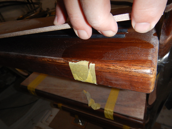
Just say no to varnished ladder treads. These treads do have some imbedded rubber strips, albeit not on the edge where it’s most needed, however, those wouldn’t be necessary if the tread was unvarnished.
Unvarnished teak has been used for decks, and ladder treads for centuries aboard seagoing vessel because, in addition to its resistance to rot, it offers superior footing, regardless of foot wear or sea conditions, wet or dry. Teak companionway treads aboard sailing vessel are traditionally unvarnished for this very reason, and other than an occasionally oiling, teak needs little or no coatings to protect it from deterioration, or to enhance its grip on bare feet, socks and shoes. The same is true of treads on steps. Adding varnish to a teak ladder or stair tread borders on blasphemous. Some might say, “What about adding non-skid to varnished treads”. Yes, that’s an option, but it’s tantamount to wetting kindling before using it to start a fire. Raw teak is about as good as it gets when it comes to nonskid; why muck with perfection? So, please just say no to varnished ladder and stairway treads.
This month’s Marine Systems Excellence eMagazine feature covers the subject of infra-red pyrometers. I hope you find it both useful and interesting.
Infra-Red Pyrometers
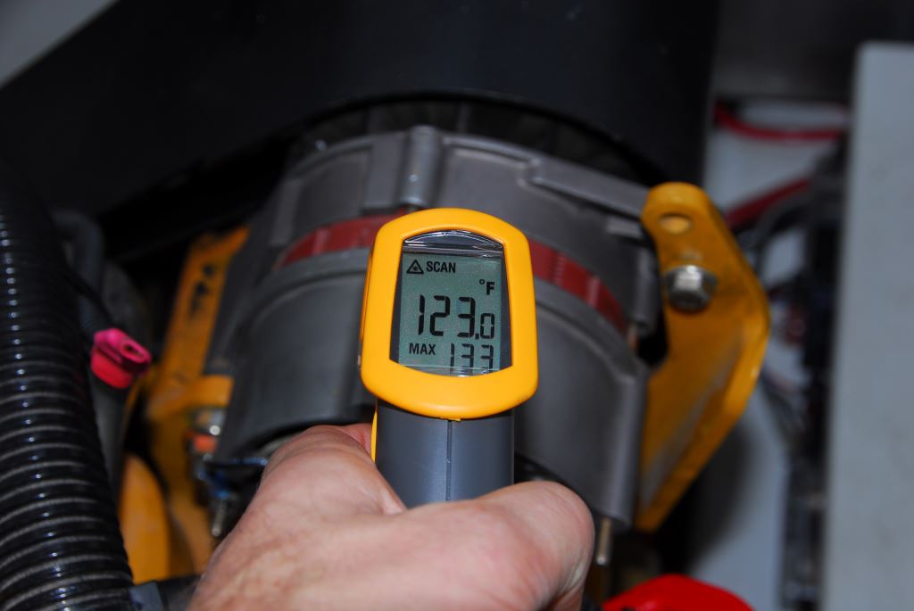
With the advent of high output charging systems, large inverters and massive battery banks, alternators have been called upon to work harder, with the consequent additional generation of excess heat. Infrared pyrometers allow users to track temperature and avoid overheating.
As a former marine mechanic and electrician, and now a consultant who carries out dozens of vessel inspections and sea trials every year, it’s hard to imagine life without an infra-red pyrometer (IRP hereafter). This tool is so valuable to me that I often carry two in my travel tool bag.
The variety of tasks IRPs can perform, and troubleshooting processes they can facilitate are nearly limitless. From the vessel operator’s perspective, one of the more important aspects of routine pyrometer use calls for the establishment of a baseline or trend on any component or piece of gear that’s being measured. For instance, if you measure the oil pan on an engine while underway and it reads 190°F (88°C) you shouldn’t be concerned because that’s within the normal range for most hard-working diesel engines. However, if, under the same operating conditions the temperature reads 220°F (104°C), still within the “normal” range for most engines, you’d have no way of knowing something was wrong unless you’d kept a record of previously taken readings. The trend analysis can be applied to the majority of items that might be read with a pyrometer, from alternator stators and belts to stuffing boxes and exhaust hoses. For professionals, the more readings you take, the more your knowledge base grows.
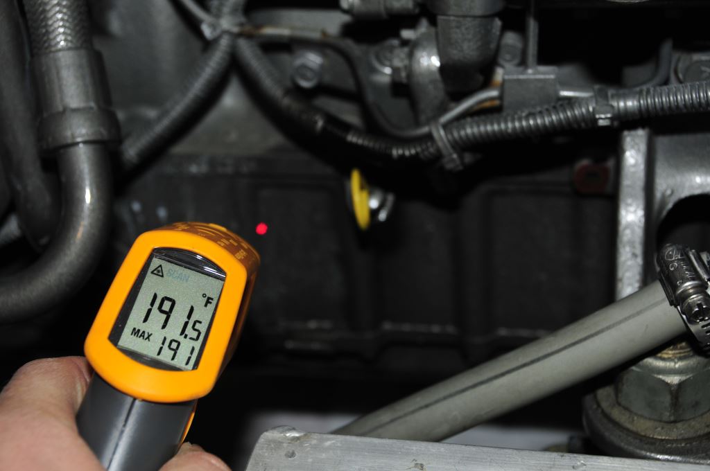
Oil temperature is most accurately measured, using an infrared pyrometer, at the vertical center of the side of the oil pan.
After measuring 100 oil pans under similar operating conditions, the one whose temperature falls outside what you are accustomed to seeing, whether or not it’s within an acceptable range, should get your attention.
Stuffing boxes are an example of a component that is especially worthy of the pyrometer’s quick and easy measurement abilities. Typically, conventional stuffing boxes, the type that use waxed flax packing, operate at no more than 40°F (22°C) above seawater temperature, dripless boxes often run somewhat cooler, thus, if the water temperature is 65°F (18°C), the stuffing box should be no hotter than about 105°F (41°C).
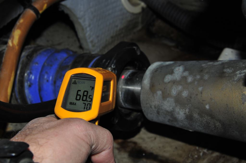
Monitoring stuffing box temperature is critical, it’s the only true means of determining if it’s working properly. When doing so, be sure not to measure the shaft which, being reflective it will skew the readings.
In many cases where an IR pyrometer might be used there are no outwardly visible clues. Take, for example, an alternator installation I encountered a few years ago on a small cruising vessel. As I ran my pyrometer over various parts of the engine, the temperature of the alternator seemed unusually high, over 250°F (121°C) after just fifteen minutes of run time. Upon closer inspection I discovered that the alternator was equipped with a unidirectional fan that was designed for rotation in the direction opposite from that which it was turning, i.e. it was designed for a right hand rotation gasoline-powered engine. As a result, instead of drawing cool air through the alternator and expelling it at the fan, the fan was now attempting, and failing, to draw air in and push it through the alternator’s body, resulting in an overheating alternator.
Even properly specified and installed alternators benefit from the regular attention of a pyrometer. Establishing a trend for the temperature of the stator as well as the diodes and bearing carrier of the alternator will often call attention to an impending failure. Include in your measurements the temperature of the pulley and the belt.
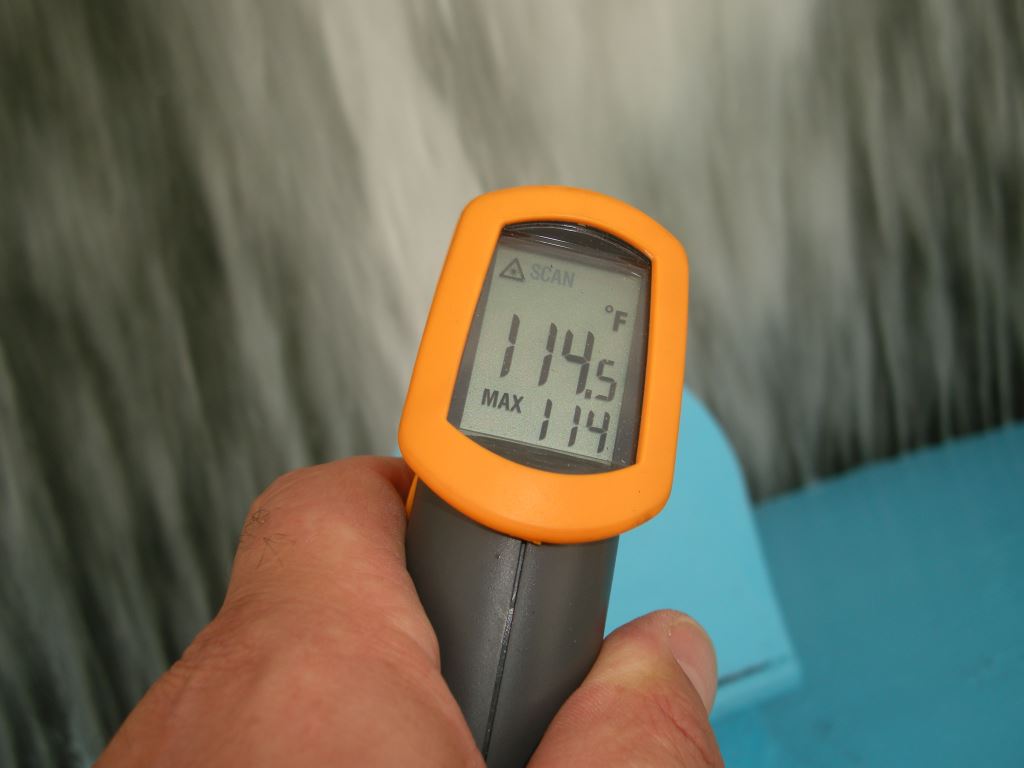
Infrared pyrometers can be used to accurately measure the temperature of liquid, including seawater.
While it seems counterintuitive, because of the volume of water that’s being pumped (it’s not unusual for a 400 hp engine to pump over 70 GPM at cruising rpm) the change in temperature for water entering an engine and that which leaves the engine is relative small, usually about 15°F (8°C). If the water leaving the heat exchanger or entering the wet exhaust is significantly hotter than this differential, then it’s likely something is wrong. Insidiously, the engine may not be overheating, yet; however, it’s likely the flow rate is diminished because of a partially restricted intake, an occluded heat exchanger or exhaust elbow or a damaged impeller. Using an IR pyrometer to identify this impending failure involves measuring the temperature of the raw water as it enters the engine, typically at the hose where it enters the heat exchanger, and again where it leaves the heat exchanger or where it enters the exhaust elbow, taking measurements on the hose. The heat of the engine room will have an effect on these temperatures; however, in this case the difference rather than the absolute temperature is the issue. The same type of differential measurement can be taken to measure the efficiency of an after-cooler.
Yet another area worthy of attention is the exhaust system. It’s not uncommon for vessels to suffer from an overheating exhaust system while the engine operates well within the normal range. The temperature of the dry exhaust gas of a heavily loaded diesel engine can be as high as 800°F to 1,200°F (427°C-649°C). Thus, any sections of the dry exhaust that are not water cooled or jacketed must be well insulated to ensure that no exposed portion exceeds 200°F (93°C). The test using a pyrometer should be conducted, carefully, after the vessel has operated at approximately 90% load, for a minimum of 15 minutes.
The dry portion of this exhaust system is too hot; the threshold for any portion of an exhaust system that can be touched is 200° F (93°C).
The wet portion of the exhaust should also be checked, no portion of it should exceed 200°F (93°C), however, in my experience a temperature this high is indicative of a problem. Typically, a properly functioning wet exhaust system hose operates at somewhere between 90°F (32°C) and 140°F (60°C). The hose section of the exhaust system should be checked using the pyrometer, from, and especially immediately after, the injected elbow to and including the muffler, and tests should be conducted after the vessel has run at cruising speed (approximately 75% load) for 15 minutes, and then descending from wide open throttle at 200 rpm intervals, dwelling at each rpm stop for a minimum of five minutes, down through idle speed. Interestingly, higher temperatures are often recorded at lower rpm, when less water is being pumped, often between the 11:o’clock and 1:00 o’clock position on the hose, so be especially vigilant at these lower speeds.
While IRP’s are invaluable, they are not fool-proof. Because they rely on shifting wavelengths of light for calculating temperature, they can deliver erroneous readings when measuring highly reflective surfaces such as stainless steel, aluminum and chrome.
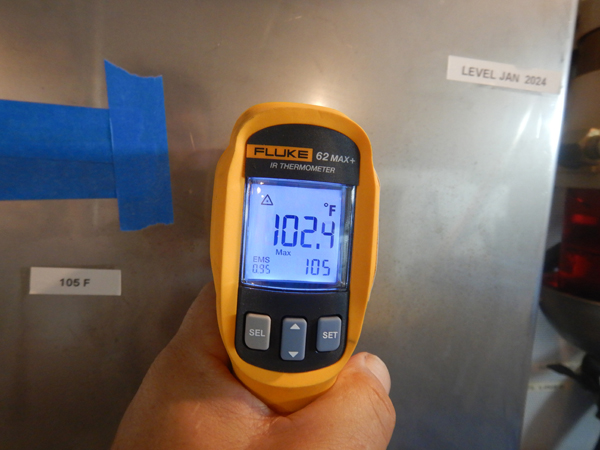
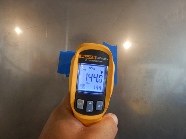
As versatile and accurate as IR pyrometers are, they can be fooled by highly reflective surfaces like stainless steel, chrome and even reflective insulation, with a resultant inaccurate reading that is typically lower than that of the actual temperature. This can be overcome by applying dark or non reflective paint or tape to the surface that is being measured.
The surfaces that yield the most accurate readings are non-reflective, flat black is ideal. Black tape or flat black paint can be applied to otherwise reflective surfaces to circumvent this phenomenon. Additionally, the measurement foot print of an IRP is not, contrary to popular belief, the miniscule aiming laser dot, instead it is a cone that grows as the distance between the IRP and the surface increases, averaging everything within that circle (a cone calculation diagram is printed on every IRP I’ve owned).
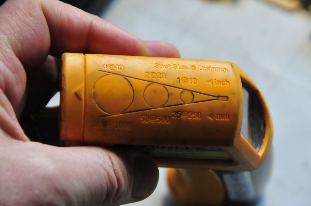
The measurement “footprint” of an IR pyrometer is cone shaped, and thus the farther the gun is from the surface being measured, the larger the measurement area, and the lower the accuracy if the temperature within that area varies. Therefore, it is advisable to place the gun as close to the surface being measured as is safely possible.
Therefore, it’s best to get your IRP as close as possible to the surface being measured, even touching it if it’s not too hot, and not moving.
Today, for the cost, it’s tough to justify not owning an IRP, or two.

