
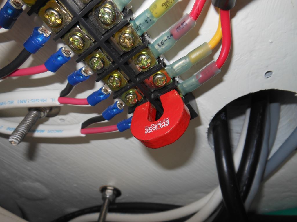
Photo Essay: Terminal Strip Design
The average contemporary cruising vessel, power or sail, is filled with miles of wiring and hundreds, if not thousands, of solderless or “crimp” connectors. If the wiring and terminals are installed correctly, they are exceptionally reliable. However, that is regrettably not always the case.
Achieving electrical reliability is a combination of proper material selection, installation technique, and standards compliance; two out of three isn’t good enough. In the accompanying image, a cadmium-plated, mild steel terminal strip has been used, and it is installed in flybridge location. While the conductivity of steel is considerably less than copper, for low current applications like this, it is acceptable. However, in a maritime environment, on what is essentially a weather deck, mild steel, because of its propensity to rust, and regardless of plating, is undesirable at best in electrical applications.
Ideally, solid copper, preferably tin plated, should be used for terminal strips and bus bars in all shipboard applications. If used on a weather deck, the completed installation should also be sprayed with a corrosion inhibitor such as CRC Heavy Duty Corrosion Inhibitor.
Ask Steve
Steve,
Recently our marina experienced a boat fire, which was likely caused by an over-loaded 30a connector. This is the third time I have experienced such fires; each event resulted in catastrophic loss, except for one where the pedestal end caught fire.
I have been reading about the Smart Connector which claims to be less prone to problems due to increased contact area of conductor pins and secure mechanical connection.
What is your opinion on this approach, over the conventional twist lock secured with coupler and protected from corrosion by dielectric grease?
Could a hard wire connection protected by a water-proof junction box, located in a locker with good strain relief solve the basic resistive connector issue?
In my application, I never remove my shore power connections aboard the boat other than for inspection. They are below decks protected from rain or spray. The power cords are disconnected at the pedestal and stored in a locker space.
Thanks for sharing your broad marine expertise with the boating community.
Rob Baker
Rob:
The SmartPlug system has been around for a number of years and it has made significant inroads towards improving shore power safety at the boat end. The traditional NEMA twist lock design, which was established before the US entered WWII, has drawbacks, especially when misused. In many cases, overheating occurs when the plug is not fully engaged in its boat-side socket, thereby reducing the surface area of the contact. Or, the locking ring is not used (or it is missing all together), which allows the plug to partially disengage, and without the locking ring the plug’s watertight integrity is diminished.
The SmartPlug, starting with a clean design slate has, for the most part, been able to overcome these issues. With large, oversized, flat blades, contact area is more than sufficient to prevent heat generation, and the integral, passive locking mechanism makes it nearly impossible to use it incorrectly. I recommend these plugs on every new build and refit project with which I’m involved.
If used properly, and kept clean, and the locking ring is used, the legacy plug can be safe, however, dielectric grease will attract dirt, which can increase resistance, and lead to heat generation, so that should be used with caution. If, as in your case, the plug is not disengaged at the boat end, then there is less risk in using dielectric grease and dirt contamination, although in a protected location, I’m not sure it’s necessary. More importantly, the vessel side inlet should be removed and its wire terminals closely inspected for corrosion, looseness or any signs of heat generation. This is a common area of heat generation. Because these connections are permanent, they can be made using dielectric grease, if you wish.
Hard-wiring the shore cord to the vessel is another option, it’s much the same as a cord reel system. This would eliminate altogether the plug and inlet interface and the risk it presents. However, and once again, if the plug and inlet are both inspected, including the wiring for the inlet, and are found to be in good condition, and they remain connected and protected, and they are periodically inspected, I don’t believe a hard wire conversion is necessary; it would be atypical. If you are considering that, I’d simply convert to a SmartPlug.
I have written, and lectured, about shore power safety on many occasions; here are a few links…
- https://stevedmarineconsulting.com/october-2011-newsletter/
- https://stevedmarineconsulting.com/neutral-to-ground-demystified/
- https://stevedmarineconsulting.com/electric-shock-drowning-and-elcis-explained/
If you search <shore power safety> on my website, you’ll find others.
Hey Steve,
Thanks for all you do for all us boaters out there.
I recently changed the zincs in my 3208. It had been about a year since I last changed them. I noticed very little erosion on them so I cleaned the threads with a wire brush to make sure they had good electrical contact. I installed the new zincs and thought it a good idea to measure the resistance between them and the engine block. I was surprised to see that not only were they open to the block but measured open between the two zincs. From my understanding, the zincs need to be connected to the bonding system to be effective.
I did some research online and asked the question on a couple of forums. I was very surprised to find out that the cap assembly that the zincs mount in is plastic and the best info I could get says that the bonding happens through seawater. Once I opened the seacock I measured between the two zincs are got about 50 ohms. Still nothing to the block.
I surmise this is as designed but am having trouble getting over the fact that there is no “low resistance” connection to the vessel bonding system.
Can you explain what is going on here and how this system could be effectively the way it is designed?
Thanks much in advance.
Greg Cyr
Greg:
In order for an anode to work properly, it must have electrical contact with the metal that is being protected, what is referred to in corrosion parlance as the cathode, to complete the circuit. Protection is complete when you have an anode, a cathode, which are both electrically connected, and immersed in the same electrolyte, seawater in this case.
If this cap is like others I have seen, while it is plastic, it has embedded in it a copper strip that is connected to the anode port’s female metallic threads, and to one of the mounting bolts, which completes the circuit with the metallic heat exchanger. If, when fully assembled, you do not have continuity between the anode bolt head, and the heat exchanger body, something is wrong. It sounds as if that interconnection between the anode and the heat exchanger may be compromised.
For ABYC E-2 compliance, the maximum allowable resistance that can exist between anode (zinc) and cathode (the protected metal), is a scant one ohm.
You should avoid using metallic brushes on this equipment, as it can deposit metal that is cathodic to the metal you are cleaning. Instead, use a non-metallic cleaning option such as a 3M ScotchBrite pad and contact cleaner.
Keep in mind, the continuity between the heat exchanger and the vessel’s bonding/DC grounding system, while present (with rare exceptions, the engine block should be at the same potential as the DC negative, DC grounding, and AC safety ground systems, however, those are related to safety and not corrosion), is not of great significance where corrosion is concerned, because the hull and the heat exchanger reside in different ‘bodies of water’, and therefore have no interaction with each other as far as cathodic protection is concerned. In other words, the heat exchanger’s anodes don’t protect through hull’s underwater metals, and the hull’s anodes don’t protect the heat exchanger.
More on corrosion and cathodic protection here.
Hi Steve,
I have read that good ventilation helps keep a holding tank healthy and promote the enzymes that break down the black water.
I have a 48′ Kadey Krogen with a 90-gallon black water holding tank. It has a single 3/4″ vent line that exits on the starboard side of the bow. I am considering adding a second vent line that would exit on the port side of the bow. This would create a good cross flow of air circulating in the tank.
Do you think there is value in doing this modification? And would it accomplish my goal?
Thank you,
Jeff Robinson
Jeff:
Port and stbd holding tank vents are beneficial and worth the effort; they will allow cross ventilation to occur. If you could increase the hose diameter, to 1.5”, that would be even better. You’ll find more on the subject here.
Alternatively, or additionally, you could install a Sweet Tank system (mentioned in the above article). This is an active, rather than passive, ventilation system. It relies on an air pump that is designed to operate continuously. This keeps the tank and effluent within oxygenated, thereby preventing the most odoriferous type of bacteria from thriving.

