Text and photos by Steve D’Antonio
Copyright © 2017
From the Masthead
There are few things I enjoy more than cruising, particularly in remote locations. Not only does this fulfill a personal need, it enables me to remain fresh and sharp, to see, feel and think what my clients and readers are experiencing. While I’m able to do this to some extent on the many sea trials I conduct every year, those are essentially snap shots of cruising. Being aboard and underway for weeks at a time, on the other hand, affords me a wider range of experiences, from long range engine operation and charging system evaluation, to cabin layout and which appliances work best. Toward that end, when you read this, and for the next few weeks I’ll be aboard NIKITA, a Fleming 65, departing from Denmark and wending my way through the Norwegian fjords. I’ll post updates while underway on the SDMC Facebook page.
Safety
The word, “safety” is used a lot in this business, too often inappropriately in my opinion. Bear with me. When it comes to building, and operating a seagoing vessel, safety is, or should be a journey, one that never ends, rather than a goal that one reaches. Several parties may bear the guilt for this, boat builders, equipment manufacturers and most of all boat owners. Many are under the impression that one can somehow buy safety, if you have enough inflatable PFDs, EPIRBs, PLBs and AEDs, you will achieve safety. No one would argue safety gear like this is valuable, however, it does not supplant other responsibilities.
In many of the lectures I deliver, and articles I write, I make a conscious effort to avoid using the word ‘safety’ as a stand-alone notion, instead I prefer the phrase “seaworthy, reliable and safe”. I do so in the hope of dispelling the belief that safety is something that can, once again, be purchased, something that exists in a vacuum, on its own irrespective of other circumstances, skill-sets, experience, equipment and operating conditions. Remember, safety is a passage not a destination, one you are on as long as you are on the water.
Apropos of this subject, the length of time between the small craft depicted in this video going from, ‘having trouble making progress’ to ‘rolled with crew ejected’ is sobering. While it’s all too easy to Monday morning quarterback, it’s hard to resist, at least constructively. While there are lessons to be learned regarding the speed with which things go from unpleasant to life-threatening, the precursors that lead up to disaster are many, and they took some time to occur, and many are of the crew’s own making, failure to check the weather forecast, a shredded main, fouled jib sheet, a lee shore or fixed pier, and worst of all, the outboard stowed in the sail locker. Never underestimate the value of an engine in times of peril. It’s truly miraculous no one was killed.
The interesting part begins at 1:30. https://www.youtube.com/watch?v=AdYTGre3fAA&feature=em-share_video_user
In this month’s Marine Systems Excellence feature I cover the subject of bilge pump system design and installation. I hope you find it both useful and interesting.
Bilge Pump Systems; Design and Installation Details
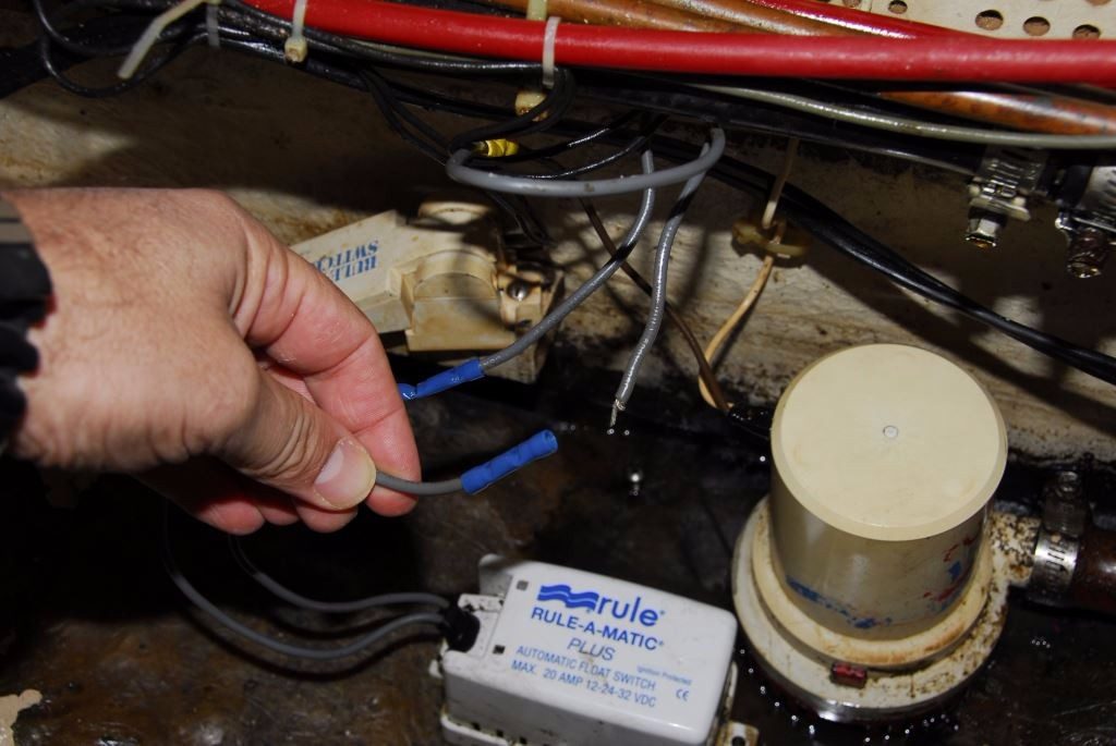
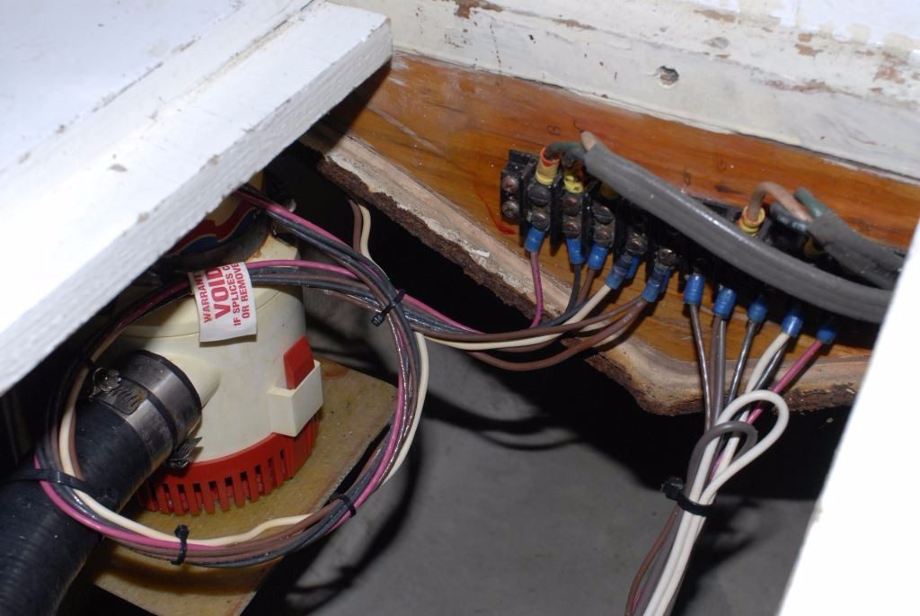
Bilge pump wiring and terminations must be rugged and robust. If connections can’t be made at least 18 inches above the base of the pump, they should be water-proof. If they can be easily pulled apart, like the one shown here, there’s a good chance the installer lacked the necessary skills to properly use a crimping tool. Without a doubt, connections this close to bilge water must be waterproof.
Most bilge pump installations are challenged on three or four fronts, wiring, plumbing, capacity and quantity or number of pumps.
Electrical
The wiring supplying electric pumps should be large enough so the voltage-drop, an inherent inefficiency that is induced over all wiring runs, is minimized. Where bilge pumps and other electric motors are concerned, the lower the voltage, the slower the pump or motor runs, and the less work it accomplishes. For critical components such as bilge pumps, the voltage drop should not exceed 3%, which means that if the batteries are fully charged and at 12.6 volts, which assumes the engine or generator are not running, the voltage available to the pump will be no less 12.2. This will diminish the pump’s capacity, albeit within what’s considered an acceptable range. It must be borne in mind, however, that all inefficiency in bilge pump systems is cumulative, and it all has one result, diminished pumping capacity, and thus minimizing it should be the primary concern of every system designer and installer.
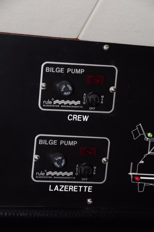
While familiar and functional, the ‘momentary on’ switch panel with fuse is less than ideal. Circuit breakers are preferred, as are continuous on switches.
In my experience, the wiring used for most bilge pumps is undersized. A pump which is located 25 feet from the battery, and draws 5 amps, requires 10 gauge wire in order to ensure the voltage drop does not exceed 3%. Few boat builders and installers take this conservative approach; smaller wire is nearly always used either by misguided design, or in simple ignorance of the recommended standards, and the detrimental results. As an aside, the electrical supply for bilge pumps should be independent of the battery switch, ensuring power remains available even when the battery switch is turned off. Each bilge pump must be equipped with its own over current protection device, a fuse or circuit breaker, preferably the latter; a group of pumps and their wiring may not be protected solely by a single device, while a master device and then sub-over current protection devices is acceptable.
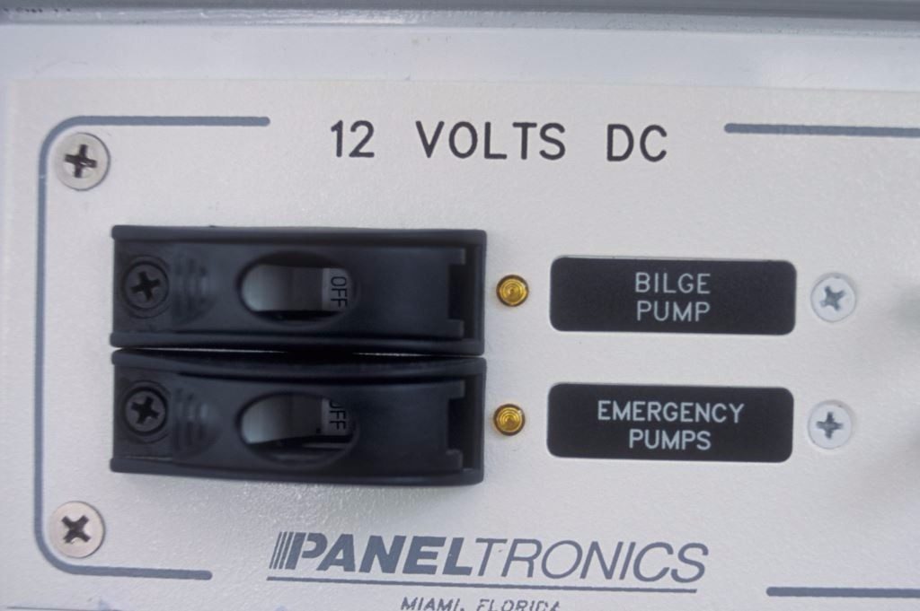
Bilge pumps and their wiring must be protected by an over current protection device such as a fuse or circuit breaker, preferably the latter for convenience sake. If a circuit breaker is used, it should be guarded like the ones shown here, to prevent them from being turned off inadvertently.
Manual and automatic switches are yet another area ripe for installation errors and poor design. All bilge pumps must be equipped with a manual switch, one that is not spring-loaded, i.e. it does not require the user to hold his or her finger on it for it for the pump to operate. This momentary on arrangement crept into boat building and design with good intentions, no doubt, to prevent folks from inadvertently leaving a pump on. However, in a flooding event, if the automatic switch fails, it’s important to be able to override it without having to resort to duct taping the manual switch in the ON position.
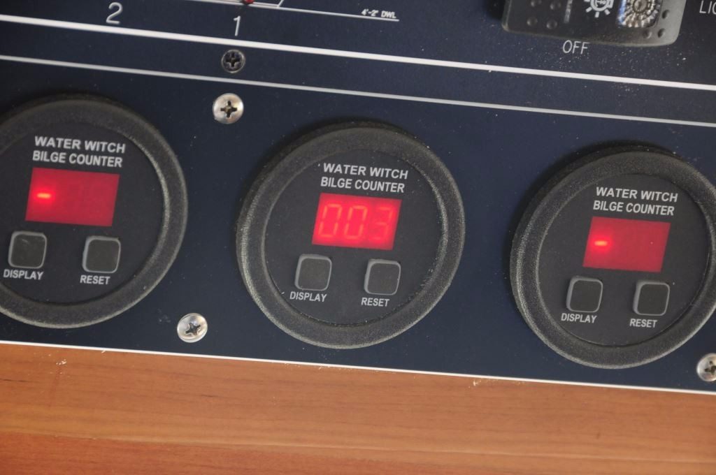
In addition to a ‘pump on’ indicator light, bilge counters can be an invaluable addition to any bilge pump installation.
Automatic float switches come in a dizzying array of styles with various actuating features and designs, with varying reliability and longevity. When choosing a switch make certain its leads are long enough to ensure connections can be made well above bilge water level. My preference is for pump and switch connections to be no less than 18 inches above the base of the pump (wires from pump and switch manufacturers should be tinned to minimize corrosion). If that’s not possible, then terminations must be fully waterproof and submersible.
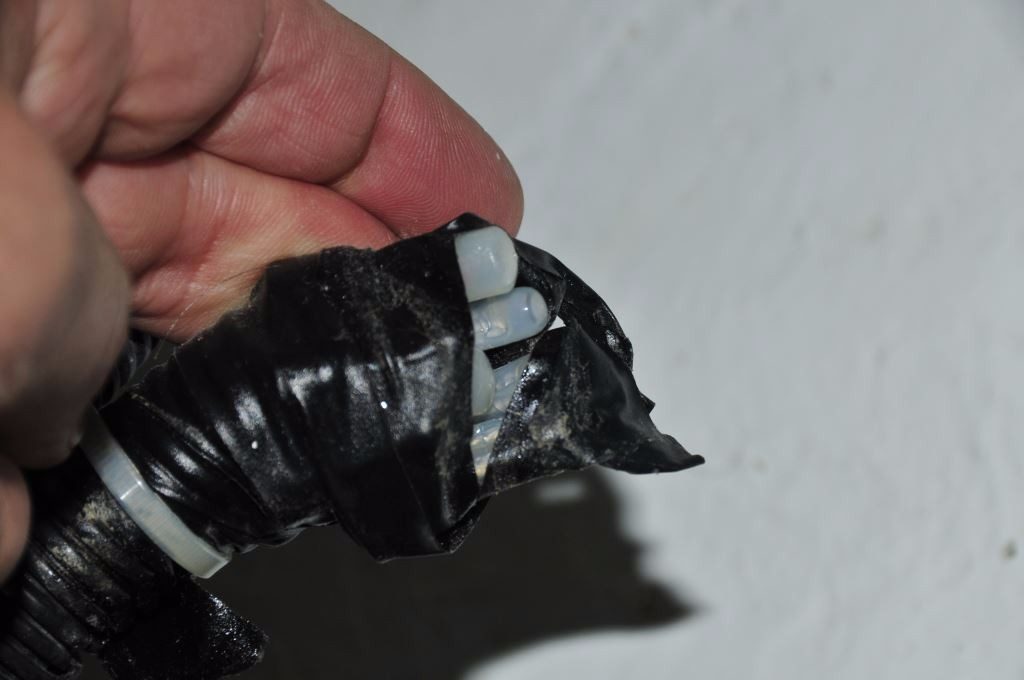
“Waterproof” means fully submersible. Connections like these, wrapped in electrical tape, will quickly succumb to immersion.
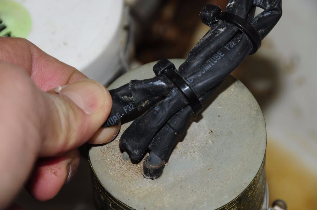
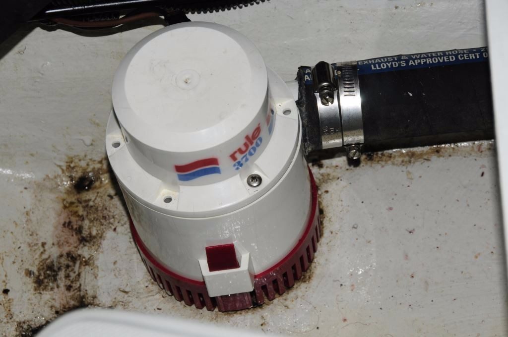
Submersible pumps should be equipped with long leads, the longer the better, to ensure connections can be made above bilge water, even in a flooding scenario. This pump’s lead has not only been cut short, its heat shrink butt splice insulation has been pierced as a result of having used the incorrect crimping tool.
The last thing you want is for your pumps to quit during a flooding event. The float switch you select should come with something more than a one year warranty; five years is preferred, as are protected, and reed switch, designs.
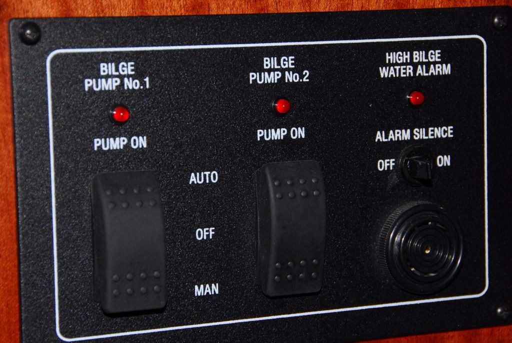
Paddle switches like the ones shown here can be too easily and inconspicuously bumped to the OFF position. Additionally, switches that defeat or silence alarms should be guarded, to prevent them from being turned off inadvertently.
Finally, bilge pump control panels should be equipped with an indicator light that is actuated by the pump itself, which means it illuminates when the pump is actually running, regardless of whether it’s triggered by the manual or automatic switch. Related to this feature, while old school, bilge pump counters are invaluable tools for alerting skippers to persistent ingress of seawater.
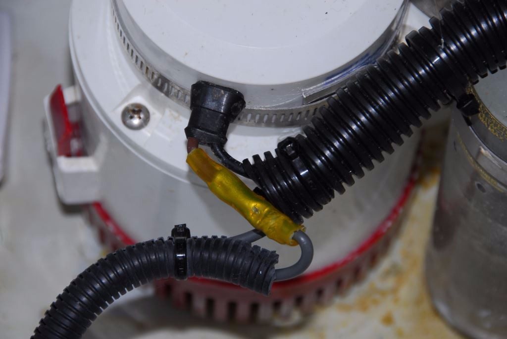
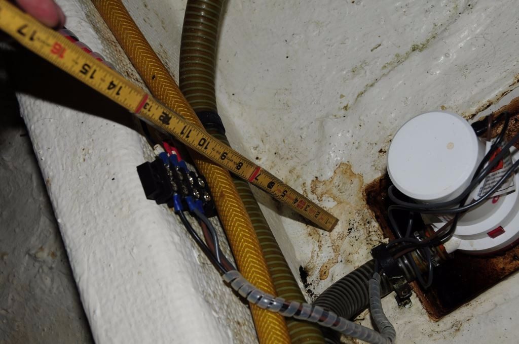
For unknown reasons, this float switch’s connections were spliced adjacent to the switch. An attempt has been made to waterproof them, however, it’s not one I’d trust, the switch should be replaced.
Plumbing
Plumbing, if improperly selected or installed, can also take its toll on a bilge pump system’s efficiency. To the degree possible, plumbing runs should be short and straight, while utilizing as few 90° bends as possible (gentle, “sweeps” are preferred). Hoses should be resistant to crushing (or vacuum induced for self-priming pumps, mentioned below collapse), and the interior must be smooth. If the outlet on the pump is one inch, the hose should be no smaller than one inch throughout its run. Under no circumstances should the hose be reduced or restricted. Many pumps use a 1 1/8 inch hose outlet. This once proprietary off-beat hose size was created by a bilge pump manufacturer as a sales tool, to force or encourage users to purchase the hose they supplied. I find this maddening, as the type of hose available in this size is limited and often neither suitable nor rugged enough; the familiar and flimsy corrugated variety should be avoided, it’s easily crushed and pierced. If you wish to avoid using this unusual size for all the aforementioned reasons, move up to a 1 ¼ inch hose, adapting couplers are available, or better yet, choose a pump that doesn’t utilize this size outlet.
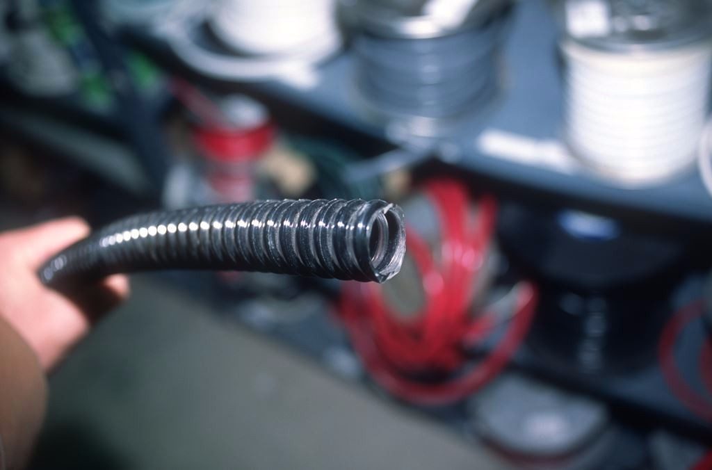

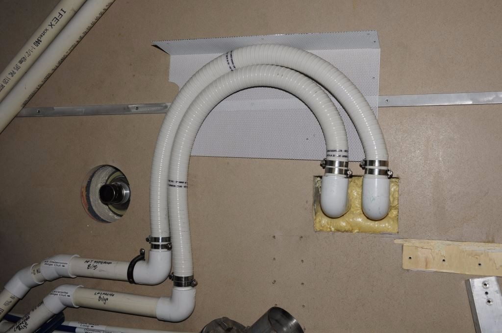
The hose used for bilge pump plumbing should be smooth on the inside, and resistant to crushing or collapsing. Reinforced, smooth wall hose (top) is ideally suited to bilge pump installations. Lightweight, thin-wall hose (above) lacks the necessary reliability and robustness for critical bilge pump systems.
If the discharge will exit the hull below the heeled waterline, then an anti- siphon valve must be utilized to prevent a siphon, and flooding, from occurring. The anti-siphon valve must be installed in a riser that remains above the heeled waterline at all times, preferably no less than 18”. For sailing vessels, this means the valve must be located on or near the centerline. When in doubt, use a riser to prevent back flooding (keep in mind what might happen if the vessel runs aground and takes on a constant list), and an anti-siphon valve to prevent siphoning.

High quality submersible pump manufacturers don’t skimp on wire length or type. This set is attached to a ShureFlo 2000 gph model.
A word on the definition of ‘waterline’ is in order; for a sailing vessel this is anything that’s submerged when heeled to the toe rail, for power vessels it’s the submerged surface when heeling 7°, in either case it’s otherwise known as the dynamic or heeled waterline. For sailing vessels, unless the discharge is in the transom, it’s likely to be below heeled waterline. Depending on the design, this may also be the case for power vessels; if discharges are in the boot stripe, as they often are, then they could very well be submerged when heeled 7°. Above all else, bilge pump discharge outlets should always be located above the static or resting waterline.
Check valves are commonly found on bilge pump installations. They are a tempting remedy for preventing water contained in a long hose run from sluicing back into the bilge, however, they are not without their liabilities.
While all too commonly used in bilge pump plumbing, a check valve should never be relied upon as an anti-siphon device and with good reason; they are notorious for failing in both the open and the closed position, which will lead to flooding and failure to pump respectively. Their use in this capacity is also prohibited where compliance with American Boat and Yacht Council Standards is sought. Check valves are also prohibited for preventing back flooding when two or more bilge pumps are plumbed to a common manifold, although such back feeding is prohibited where compliance with ABYC Standards is sought. Manifolded bilge pump systems can be tricky, among other things, in order to comply with these Standards, simultaneous operation of all pumps must not diminish the flow rate of any pump. Check valves may be used in other roles, to prevent water contained within a long hose run from flowing back to the bilge; however, if the valve is close to the pump, the pump may not be able to overcome the weight of the water on the other side of the valve, thereby insidiously disabling the pump, as the pump will run, it simply won’t pump water. As if that’s not enough, there’s one further reason to avoid using check valves, their presence can seriously diminish the flow rate of a pump, by as much as 50% in the tests I’ve carried out. My advice is to avoid the use of check valves in bilge pump installations when and where ever possible. For additional details on check valves see Check Valves.
Bilge pump electrical connections must be located well above the pump or, if that’s not possible, they must be waterproof.
As installed, pumps and float switches should be relatively accessible for inspection, cleaning and service. Keep in mind, in addition to repair or replacement, submersible pump strainers require cleaning from time to time. Pumps and switches that are semi-permanently installed in deep bilges, with no provisions for periodic removal, will prove problematic at some point. Give thought, therefore, during the design phase of an installation, to establishing a means of removal.
For high capacity in a small package, submersible pumps are the obvious choice.
Capacity
The final area in which pumps are challenged is in their capacity or quantity. Simply put, the pump’s capacity is either too small or there aren’t enough of them for a given size vessel. My Gearhead’s bilge pump rule of thumb calls for 1000 gallons of pumping capacity per hour, for every 10 feet of overall vessel length. Thus, a 40-foot vessel may be equipped with two 2000 gph pumps, or one 2000 gph pump and two 1000 gph pumps. No one ever complained about too much bilge pump capacity. Multiple pumps afford redundancy, so it’s best to avoid placing all your pump eggs in one basket.
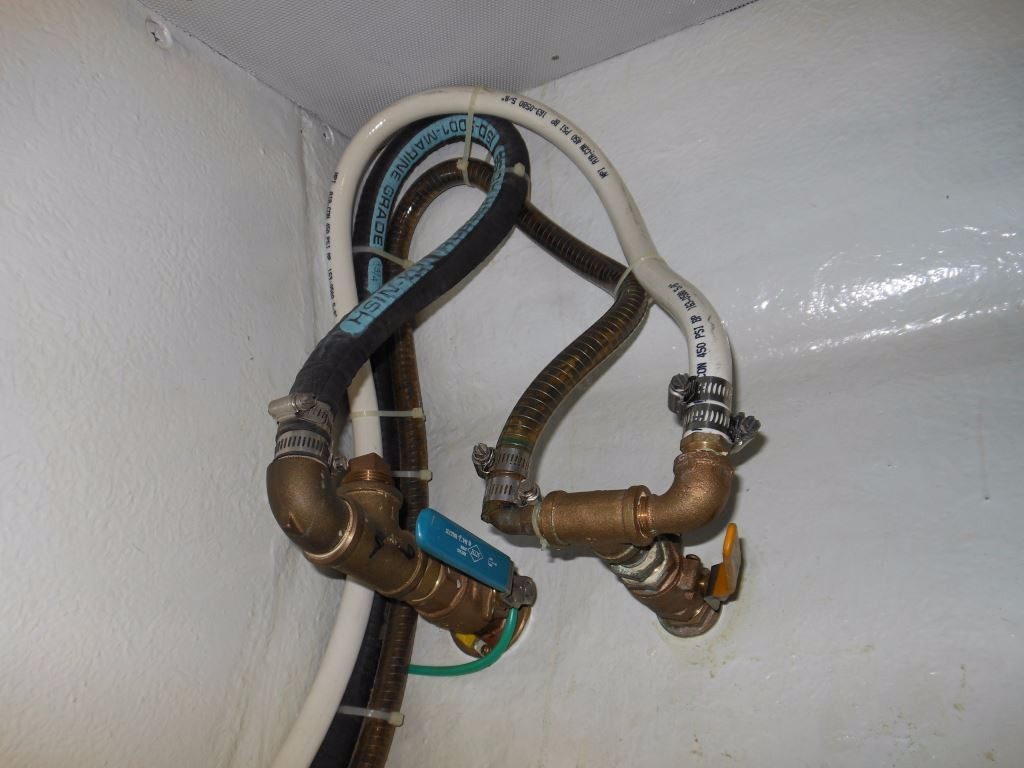
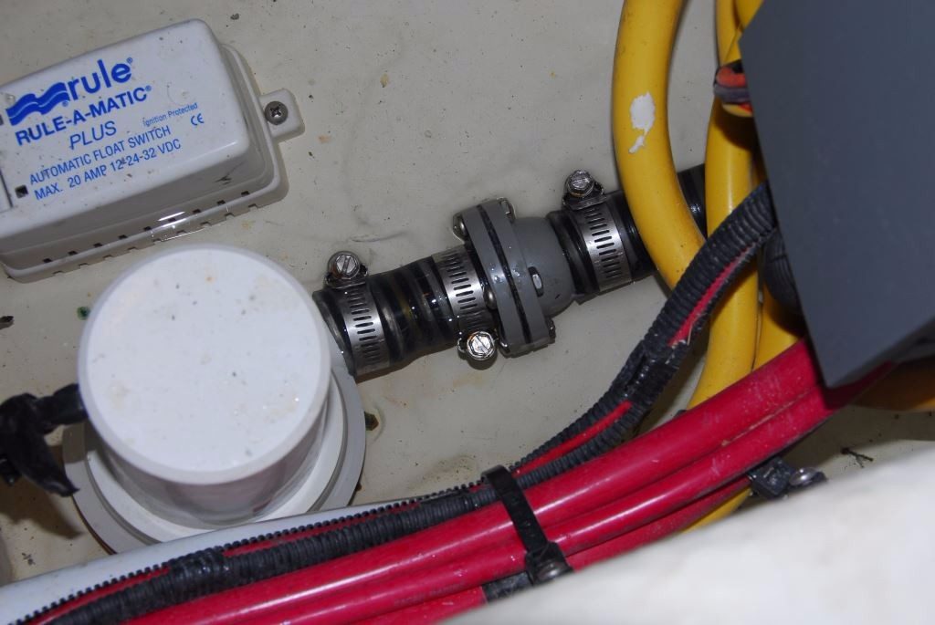
These installations carry with them a series of insidious and serious faults, including and especially risers without anti-siphon valves (above and top), and paralleled pump discharges (top). While risers effectively prevent down flooding, they do nothing to mitigate siphoning.
In order to achieve the above-mentioned capacity, pumps must, by necessity, be of the submersible, centrifugal variety. This design offers the greatest pumping capacity with the smallest footprint, and it’s capable of passing moderate-size debris; however, there is a price to be paid for these attributes. Centrifugal pumps are not self-priming, and thus their intakes must be fully submerged to operate. The larger the pump, the taller the intake strakes (these strakes act as the pump’s strainer, they must obviously be kept clear), the more water it will leave behind when it stops pumping.
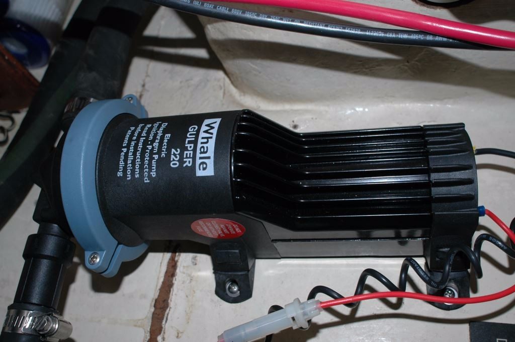
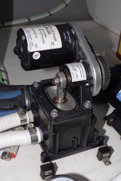
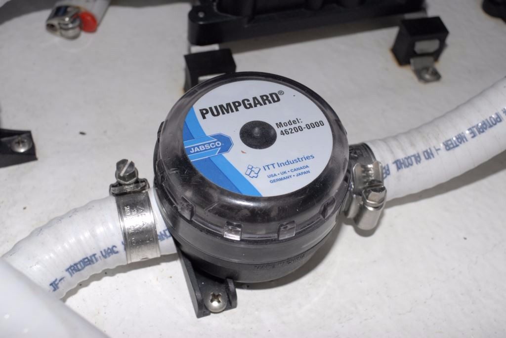
For bilge drying, a self-priming diaphragm type pump (top and middle) is often the best choice. Located well above bilge water, its pick up hose can remove water to a lower level than a submersible pump. Such pumps are sensitive to debris ingestion, and as such they must be equipped with in-line strainers (above).
If the inch or so of water these pumps leave behind (the overall quantity can be considerable in the case of wide, shallow bilges) then you may choose to install what’s known as a drying pump as well. Unlike primary bilge pumps, these typically take on the form of a self-priming, diaphragm-style pump. The pump itself is located out of the bilge, well above normal bilge water level. The capacity of these pumps is low, typically in the hundreds rather than thousands of gallons per hour, however, their strength lies elsewhere; because of their remote pick-up design, they are capable of removing water down to fractions of an inch, leaving a bilge relatively dry. Because they use a diaphragm(s) and check valves, they are far more sensitive to debris than their centrifugal brethren, which is why they must be equipped with in-line strainers, which in turn must be inspected and cleaned regularly. One of the most common causes of a bilge pump’s failure to work properly is fouling from bilge debris. Therefore, clean bilges represent more than just good housekeeping, they ensure reliable bilge pump operation, particularly in the event of flooding when wood chips, wire remnants, wire tie clippings and other cast off material is most likely to be washed into bilges.


Dirty bilges are simply an invitation to clogged bilge pumps. Clean bilges are, therefore, critically important in order to ensure bilge pump reliability.
Finally, the only way to ensure bilge pumps and float switches operate properly is through controlled bilge flooding. Using a garden hose flood your bilges to make sure this gear triggers and pumps properly. Simply actuating the pump manually or by lifting a float switch does not ensure the pump will actually remove water. I’ve encountered precisely this scenario where a discharge seacock had been inadvertently closed, or a check valve was stuck in the closed position. The pump runs and the water around it is agitated, affording the appearance of work, when in fact no water is removed from the bilge.
If you wish to determine your actual pumping rate, which will nearly always be below any individual pump’s rated capacity (while this is changing, many pump manufacturers still rate capacity under ideal, i.e. not real-world, conditions, with no head or lift, and at charging rather than resting battery voltage), disable pumps while adding a known quantity of water to the bilges. Then, turn the pumps on and measure the time it takes to evacuate the water. With a little simple arithmetic you can then calculate your as-installed capacity in gallons per hour.

