
From the Masthead
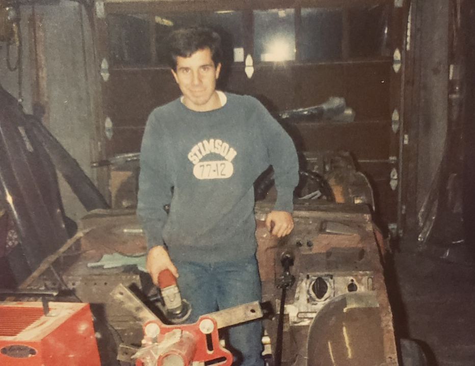
I began working in the marine industry as a mechanic and electrician back in 1988. At that time, I was in the midst of a years-long restoration of a British sportscar, a 1974 Triumph TR6, one I own to this day. I literally disassembled it down to its most basic body components; there isn’t a nut or bolt that hasn’t passed through my hands, at least twice.
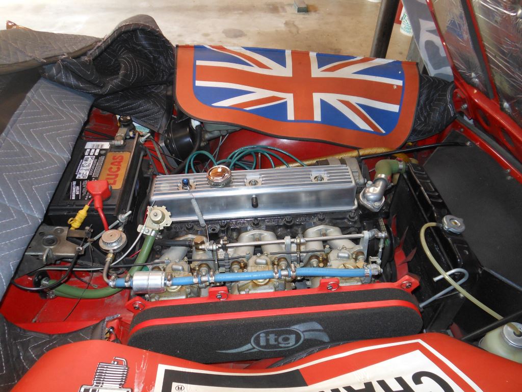
When the engine block came back from the machine shop, I carefully reassembled it, then just as carefully masked off all ports and openings, then “washed” it with solvent, after which I applied six coats of gloss black enamel. After all of the painting was complete, I installed the accessories, including the wiring harness, hoses, and belts.
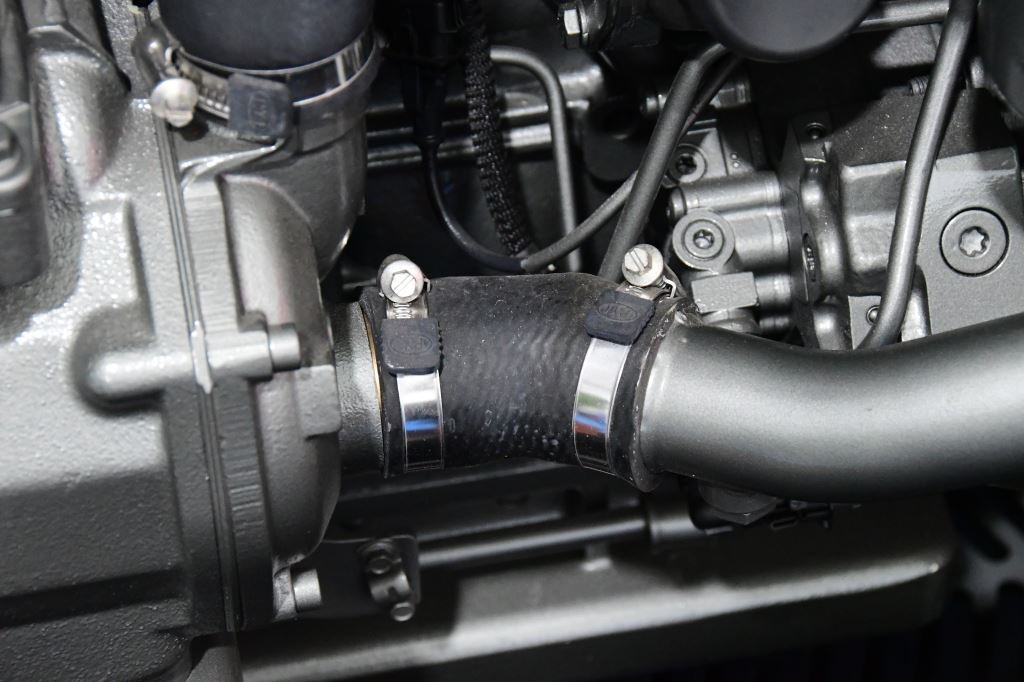
There is no good reason to paint hoses and hose clamps, and unpainted just looks better.
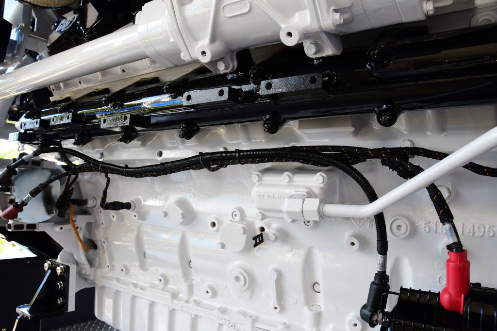
Marine engines and engine rooms are often a focal point for a vessel and its owners, (and who can blame them), and the bar for these spaces only continues to rise with each passing year. Engine rooms are brighter, cleaner, neater, and more welcoming to gearheads; however, many engine manufacturers are still painting engines as a finished product, including, much to the frustration of many, hoses, wiring harnesses and even belts in some cases. Painting flexible components like these is problematic at best, the paint typically begins to crack and flake off after just a few months of use, if it hasn’t already begun to do so when new. It becomes unsightly, with paint chips seemingly forever accumulating around and under the engine.
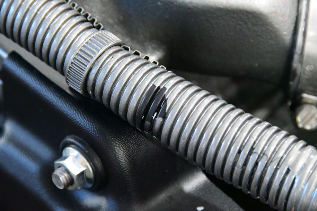

Paint does not adhere well to flexible components like hoses, wire and loom.
While attending the 2022 Fort Lauderdale Boat Show I paid close attention to this issue, and I asked several engine manufacturers if they were aware of the problem, and if they were willing to paint engines before hoses and wiring harness were installed. Most didn’t quite know what to make of the request, but eventually said no, that’s the way the engine comes.
More engine manufacturers should offer at least the option of not painting wiring and hoses.
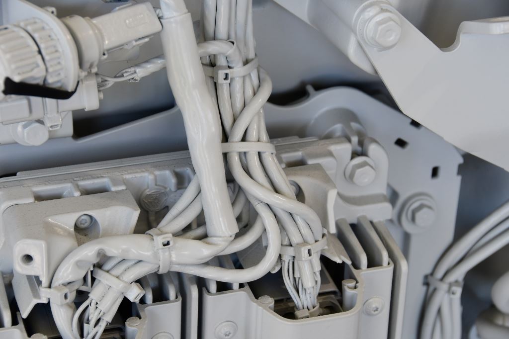
At least one, however, Caterpillar, specifically offers an option for unpainted wiring harnesses and hoses, at the time I inquired it was $600. I’m hopeful other engine manufacturers will pay attention to this and follow their example.
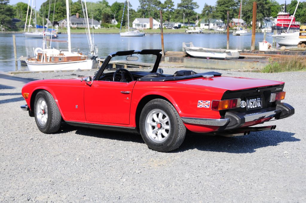
As for the Triumph, I completed the restoration after three years, with paint-free wiring and hoses.
This month’s Marine Systems Excellence eMagazine column covers the subject of Dry Exhaust Systems, I hope you find it both useful and interesting.
Dry Exhaust System Details
Many commercial, as well as a smaller number of recreational vessels, are equipped with fully dry exhaust systems. That is, they use no seawater within the vessel what so ever. The debate about their advantages and disadvantages remains an active one, with ardent acolytes, both users and designers, on both sides.
I’ll begin with what isn’t debatable; a full dry exhaust system conveys exhaust gasses from the vessel’s engine to a discharge, typically a stack of some sort, using insulated metallic pipe (the pipe can be mild steel, or stainless steel, if the latter it must be 316 for ABYC chapter P-1 compliance). The system is often used in conjunction with, or in support of, a keel cooler. These two systems make it possible to do away with all engine-associated raw water components. Coolant is circulated through the hull-mounted keel cooler, making the water in which the vessel floats in effect the “heat exchanger”, and of course no raw water is needed to cool the exhaust.
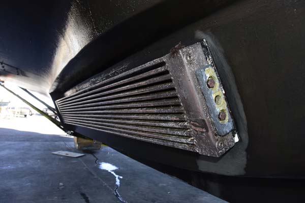
Keel coolers can be thought of as a heat exchanger that’s immersed directly in seawater, which eliminates the raw water pump, seacock (it still uses through hulls, but not valves) and associated plumbing.
Why Use Dry Exhaust
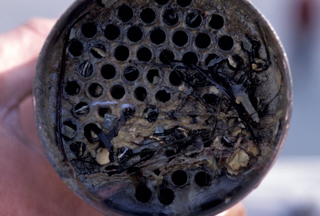
The advantages to such a system are the elimination of the raw water system, seawater strainers, pumps, impellers, hoses, water lift mufflers, seacocks, heat exchangers, exhaust mixing elbows, and the maintenance and potential failures associated with all of these items. While it can be argued the system requires less maintenance, it is not maintenance-free. The engine’s closed cooling system must still be flushed and coolant periodically replaced, that would be necessary with a wet exhaust system as well, and keel coolers must be cleaned. Most keel cooler manufacturers recommend against the of use anti-fouling paint. If used regularly keel coolers tend to remain relatively free of growth, however, if left idle for long periods in high growth areas, as many vessels are, fouling is common, making cleaning a necessity, and it isn’t necessarily easy, as keel coolers often incorporate narrow slots, that are ideally suited for hard growth, and challenging for divers and yard personnel to clean. Keel coolers are usually equipped with sacrificial anodes, which must be replaced periodically.
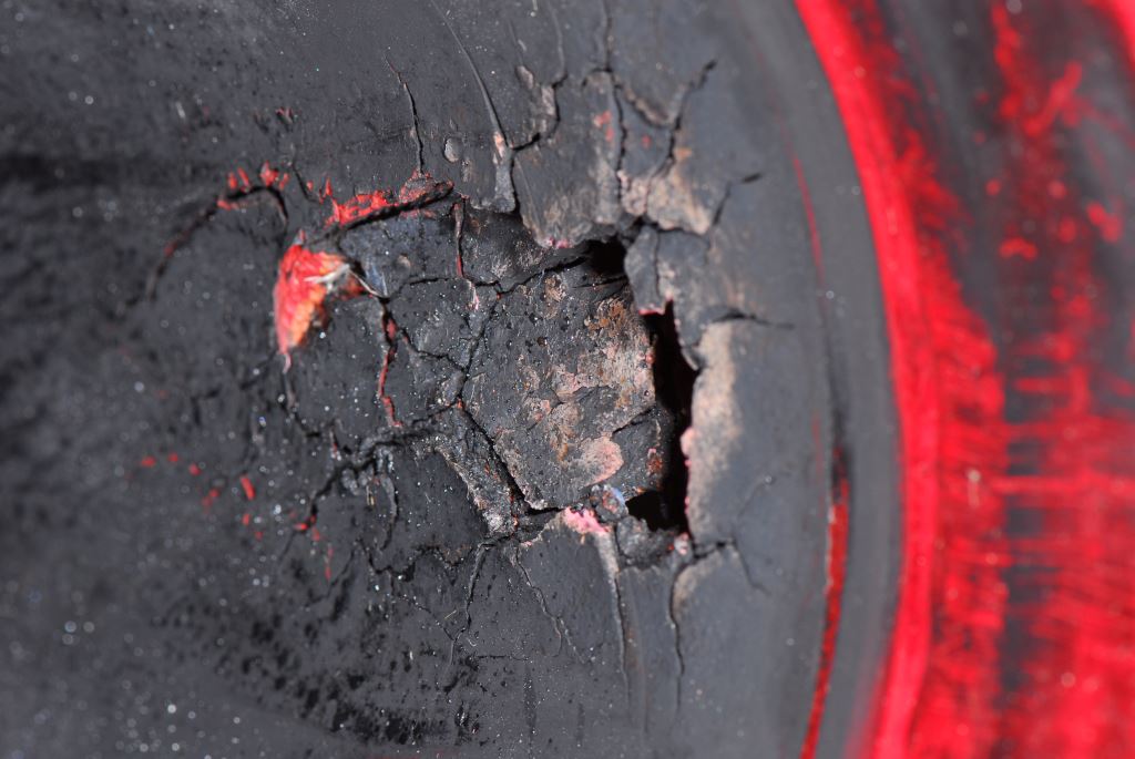
This wet exhaust hose was burned, and ultimately pierced, when its engine’s raw water supply was restricted.
Dry exhaust systems should be inspected for leaks, soot, and deterioration of insulation and support mechanisms. A dry exhaust will leak exhaust gasses, which can be difficult identify, while a wet exhaust will usually leak gas and water, the latter is easier to identify, so leaks in wet exhaust systems rarely go unnoticed. Again, inspection would be necessary on a wet exhaust system as well. Unlike a wet exhaust system, however, dry exhausts can and often do produce soot at the stack exit, especially at start up, which is problematic for recreational vessels with white or teak decks, as soot particles rain down on them (or those of slip neighbors); if the deck is wet with dew, spray or rain, it can be especially difficult to clean. Some operators resort to placing a butterfly net-like device, or panty hose, over the exhaust discharge at start up to capture particulates.
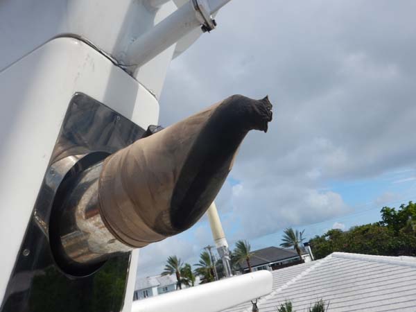
Some dry exhaust users resort to extreme means to prevent soot proliferation, here a pair of pantyhose has been placed over the outlet as a particulate filter.
Dry vs. Wet
While wet exhaust systems generally require more maintenance, and failures can lead to engines becoming flooded with and damaged or completely ruined by water, they do have one advantage over dry exhaust systems; all of the major components are inside the vessel, particularly the heat exchanger. If it needs to be repaired or cleaned, the vessel does not need to be hauled out, and many owners can do this themselves. This is not true where keel coolers are concerned. Furthermore, if a dry exhaust vessel requires repairs or replacement of the muffler or associated heavy piping, the “stack” surrounding this pipe must be removed or at least partially disassembled, and these components lifted out of the recess, often requiring the use of a crane. Depending on the size of the system, this almost certainly requires the vessel to be hauled, and in a yard.
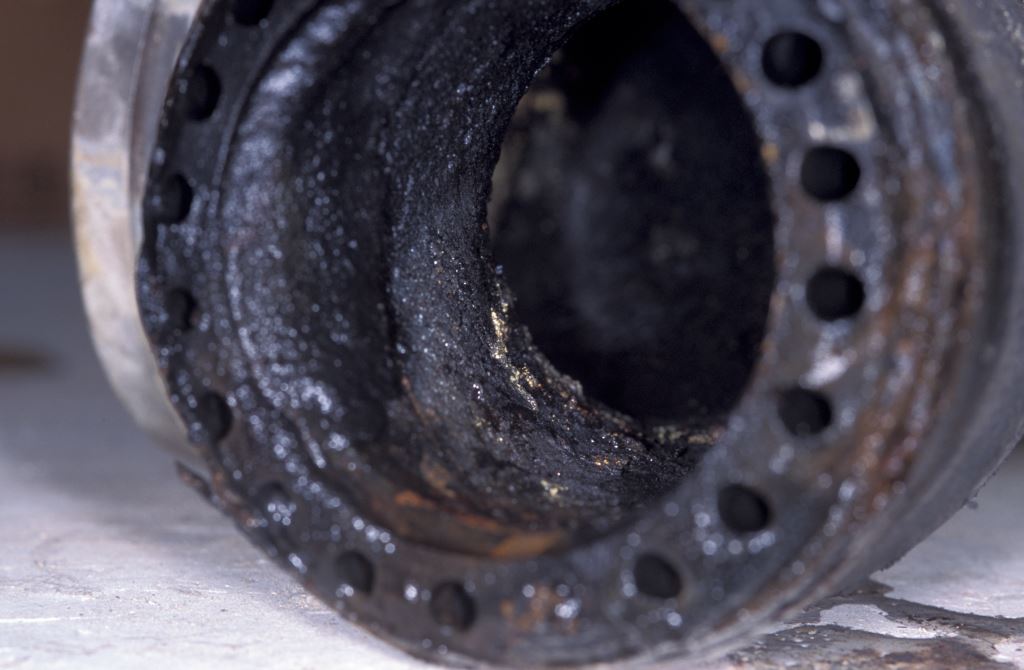
Wet exhaust systems aren’t without their woes, here a mixing elbow has corroded and is leaking, potentially into the engine, where the damage could prove irreversible.
The challenges for dry exhaust systems contend that, among other things, the vessel must be designed around the exhaust pipe(s) and muffler, which typically pass through accommodation spaces. These must be insulated against the transmission of heat, noise (dry exhaust vessels are nearly always louder while underway, especially in a flybridge if so equipped) and vibration, and they occupy otherwise valuable interior space, often through the middle of the vessel for a single screw application. For this reason it’s typically not practical to convert a wet exhaust vessel to dry exhaust, or to build a vessel that has been otherwise designed for a wet exhaust system, with a dry exhaust.

Wet exhaust system components are prone to fouling, corrosion and leakage.
ABYC Standards specify that any portion of an exhaust system whose surface temperature exceeds 200 degrees Fahrenheit (93°C), must be insulated to reduce it below this threshold, or it must be otherwise guarded or protected (see specific standard language below). I would add that not only is there a burn injury hazard, there is also a fire risk potential that must be considered, for nearby combustible material such as fiberglass, timber, wiring, plastic components etc. This requirement applies to fully dry systems as well as the dry portion of an otherwise wet exhaust system.
Dry exhaust sections require substantial insulation; in spite of that they may still radiate a considerable amount of heat.
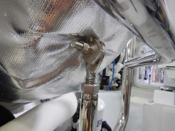
Additionally, any supports attached to the exhaust must also include a means of isolating or insulating heat transfer from the exhaust pipe to the vessel structure, particularly if it’s fiberglass or timber, as well as minimizing both burn and fire hazards.
ABYC Standards also dictate that…
- All fittings, joints, clamps, and supports of an exhaust system shall be accessible for inspection and repair; [this can be challenging depending upon the design].
- Exhaust system piping and components shall be supported to minimize the risk of failure from vibration, shock, expansion, and contraction
- All supports, hangers, brackets, or other fittings in contact with uncooled exhaust carriers shall be non-combustible and constructed so that the temperatures transmitted to the supporting materials will not cause combustion
- Protective guards, jacketing, or covers shall be provided wherever persons or gear might come in contact with the exhaust system where the temperature exceeds 200°F (93°C).
NOTE: Engine maintenance or engine repair may make the temporary removal of this protection necessary.
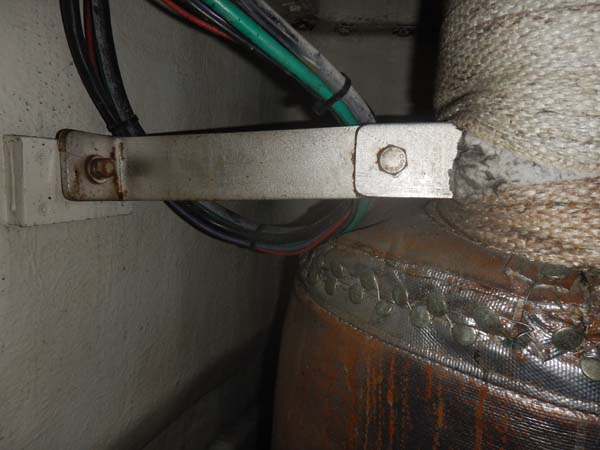
Supports for dry exhaust systems must be able to support the ample weight of the components, as well as acoustically, vibrationally and thermally insulate them from the vessel’s structure, while taking into account heat related expansion.
Radiation of heat within the engine room, and to the accommodation spaces, also present challenges for designers and builders where dry exhaust systems are concerned. When water is injected into a wet exhaust system, exhaust gasses are rapidly cooled, reducing noise considerably, typically to well under 200 degrees Fahrenheit (93°C), as well as allowing them to be transported thereafter within fiberglass pipe and flexible hose. This is of course not an option where dry exhaust systems are concerned, as the exhaust gas temperature can be as high as 1,100 degrees Fahrenheit (593°C); all plumbing must be metallic, which is invariably heavy. It must be properly supported, eliminating, or reducing, depending on the engine manufacturer’s requirements, the load imparted to the turbo-charger, or exhaust manifold flange. Supporting these loads effectively, and achieving all of these goals, presents no small challenge to those designing and building dry exhaust vessels; and failure to do so can and does result in flange or fastener failures, which in turn causes exhaust gasses and soot to leak into the engine room, creating a horrible mess at best, and potentially catastrophic scenario.
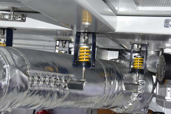
Jackscrew type supports are desirable in that they offer fine adjustment, when aligning the significant weight of a dry exhaust pipe, or dry section of a wet exhaust riser, with a turbo, or exhaust manifold flange.
Adjustable struts can be used to support the initial section of exhaust, in a fashion similar to a dry riser on a wet exhaust system. Thereafter, a flexible section of exhaust pipe must be used, called a ‘wrinkle belly’, allowing the engine to move independently of the remainder of the dry exhaust system, which is supported by the engine room overhead structure, and then the cabin structure as it wends its way out of the vessel. The latter, which is insulated pipe and often includes a heavy metallic muffler, must be flexibly mounted in order to avoid conveying vibration to the vessel, using supports that typically incorporate a spring or motor mount-like mechanism.
Although it comes at a design cost, when properly executed, a dry exhaust system can be robust, and long-lasting, making it a good choice for the right vessel.

