
REQUIRED TOOLS:
- Common hand tools
- Combination wrenches
- Large pry bar, 2×4 or hydraulic jack with spreader attachments
- Feeler gauges, preferably go-no-go variety
- Eye protection
PARTS:
- Motor mounts if being replaced
- Coupling fasteners if being replaced
LUBRICANTS, SEALANTS, ADHESIVES:
- Light liquid lubricant
- Fastener witness product such as Torque Seal
ABYC REFERENCE
- P-6 Propeller Shafting Systems
Introduction: This guideline is designed to assist you in properly aligning engine and shaft couplings. Engine and propeller shaft alignment are among the most critical aspects of propulsion system installation, reliability and maintenance. However, they are also among the most frequently misunderstood and neglected, and as a result they are frequently the source of failure and unnecessary expense for boat owners.
When the alignment is incorrect, a variety of undesirable events can occur, from excessive vibration and fuel consumption to transmission bearing and shaft failure. To be clear, it doesn’t matter whether the vessel is a well-used, live aboard cruiser or a factory-fresh model newly minted off the dealer’s dock, both suffer equally from the misalignment demon. If a propeller and shaft require excessive effort to turn while the vessel is afloat or ashore, more so for the latter as this is the vessel’s natural state, then it’s possible that a misalignment issue exists. It’s worth noting, if the vessel runs smoothly, or if the shaft is easy to turn, it doesn’t mean the alignment is correct. Misalignment is one of the most insidious of issues that can be visited upon a vessel. Therefore, take no chances, make sure the alignment is correct. For skilled professionals, the analysis part, determining if the alignment is out and if so by how much, is often quick and easy, rarely taking more than a couple of hours.
Engine vs. Shaft Alignment
It’s important to make the distinction between the two different types of alignment that exist aboard virtually every vessel. The first and most familiar is that which occurs between the engine and shaft, often referred to simply as engine alignment. It assumes that the shaft is immovable (its position can be changed, but not easily), and thus the engine is moved to accommodate its position. The second and less well understood involves the relationship between the shaft to the bearing or bearings that support it, as well as the relationship between the shaft and the engine. Most boat owners and professionals alike, when discussing alignment, are referring to the first type, that which involves the engine. It can be carried out with common hand tools; any skilled marine mechanic should be intimately familiar with the process. Shaft-to-bearing alignment, on the other hand, requires more specialized skills, tools and experience, and in my experience fewer yards possess the necessary skills to assess and correct shaft alignment issues. It will be the subject of a later task sheet.
Engine Alignment
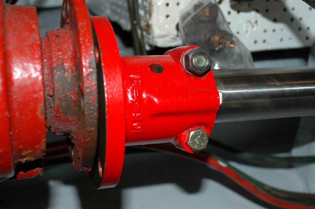
For engine alignment, the primary area of concern is the interface between the transmission output coupling and the shaft coupling. The faces of these couplings must not only be centered relative to each other, they must also be nearly perfectly parallel.
Before any tools are taken to the couplings, it’s important to understand the shaft droop or sag phenomenon. Made using alloys whose primary content is iron, shafts and couplings are typically quite heavy. Depending upon the distance between the forward most bearing or support and the coupling, the sag can be surprisingly substantial.
When I’ve discussed this issue with some mechanics they’ve expressed skepticism. As a demonstration, I had a shaft, complete with coupling, clamped to a sturdy workbench, extended past the end of the bench the same distance as that found on an example vessel, two or three feet perhaps, which induced an undeniable and measurable droop.
Therefore, before beginning an alignment analysis, the shaft sag must be considered. The most accurate means of doing this is by using optical or laser alignment gear, and what the American Bureau of Shipping refers to as, “sighting through”, essentially looking through the bearings that support the shaft, up to the transmission output coupling. Alternatively, the free hanging weight of the shaft and half the weight of the coupling can be calculated and accounted for with upward force, using a conventional or hanging scale.
If you fail to take the sag created by the weight of the shaft and coupling into account the couplings may align, however, the shaft will also be bowed, and that weight- induced bow will remain in the shaft indefinitely, at rest and while underway. Such a bow may lead to premature Cutless bearing wear and in extreme cases, shaft failure.
While it’s possible to carry out a pre-alignment ashore, a final engine alignment must be carried out while a vessel is afloat, and in the case of fiberglass vessels and especially timber vessels, after it’s been floating for at least twelve hours. Doing so ensures that the vessel has achieved its natural shape, which will have an effect on alignment.
This guideline is not a substitute for following all applicable manufacturer and ABYC guidelines, as well as recognized marine industry best practices.
PROCEDURE:
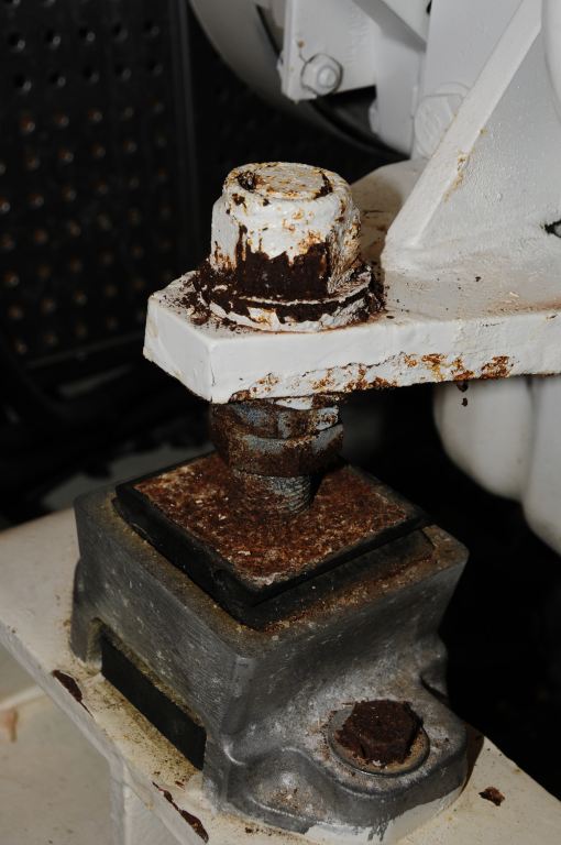
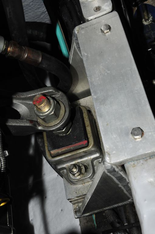
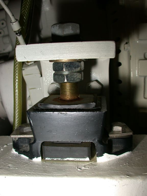
Step 1: Begin by carrying out a detailed inspection of the components associated with the alignment process. This includes the motor mounts, mount shelves or engine beds, mount fasteners, the couplings, and the coupling fasteners.
Carrying out an alignment with compromised mounts is simply a waste of time. If they, especially the adjustment stud threads and nuts, are heavily rusted, or the rubber material is cracked, separating from its metallic base, collapsed, oil soaked or otherwise deteriorated, they should be replaced. The generally accepted lifespan for a flexible mount is 10 years, if they are older than that, replacement should be strongly considered.
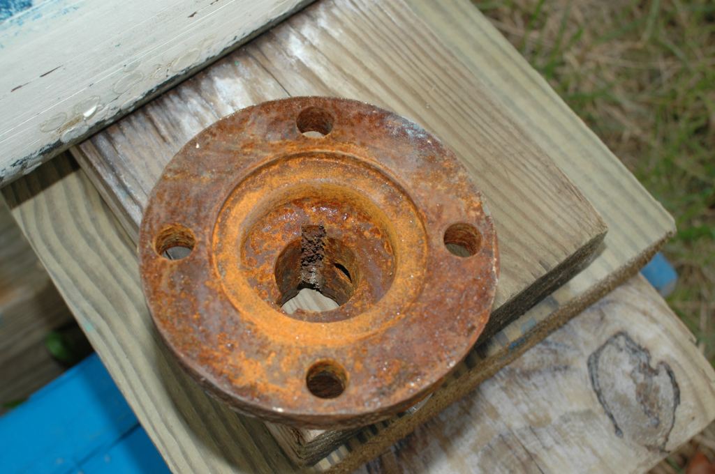
Step 2: Remove the coupling bolts and separate the two couplings. Inspect these fasteners, if they are rusty or otherwise damaged, then they should be replaced. If the couplings are rusted, these two should be cleaned and corrosion inhibited or painted. If severely rusted they may require replacement.
Step 3: Alignment cannot be checked or adjusted if a flexible or a non-metallic insert is located between the couplings. These must be removed and the coupling faces mated together in order to check the alignment. If this is not possible, if the shaft cannot be brough forward far enough to accomplish this, a precision shim may need to be temporarily installed. Once source for these is Spurs.
Note, if the shaft is equipped with Spurs line and weed cutters, moving the shaft aft will disengage the Spurs stator and rotor assemblies. It will need to be re-engaged when the shaft is moved forward for the final attachment.
Step 4: Carefully inspect all flange face surfaces, including the pilot bushing and pilot receiver, a protrusion and indentation respectively, near the center of the couplings. All should be free of dents, dings, scoring, corrosion or other damage, and they must be capable of engaging each other snugly (you can’t actually see them engage once assembled, however, the engagement can be felt, if the pilot bushing and
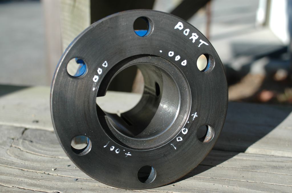
indentation into which it fits are not a snug fit, because of corrosion, damage or mismatch, the couplings may be off center, which will make alignment impossible). If there’s any doubt, and especially if the coupling has any evidence of having been hammered, it should be brought to a propeller shaft machine shop for analysis and repair. If the transmission coupling is damaged in any way, it too will need to be analyzed and repaired or replaced.
Step 5: Spray or rub onto the coupling faces, and pilot bushing, a light lubricant such as CRC’s 6-56, WD-40 or any light oil. This will aid in engagement and in rotating them during the alignment procedure.
Step 6: Pre-position the transmission output coupling using either the optical or laser alignment position of the shaft centerline. This will ensure this coupling is centered with what will be the shaft centerline. It does not achieve alignment, however, because the coupling faces must not only be centered, they must also be parallel.
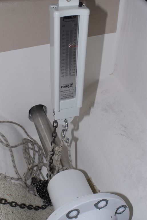
Step 7: If a laser or optical sight cannot be used (this requires shaft removal), you must then apply upward force to the shaft equal to half its overhanging weight and the full weight of the coupling. Shaft weight per foot can be found on line at shaft manufacturer websites such as this The coupling will need to be weighed. The shaft overhang is measured from the forward most support, which is usually a rigidly mounted stuffing box, or Cutless bearing mounted at the forward end of the shaft log. Some interpretation is needed here because even flexibly mounted stuffing boxes provide some support. The hanging scale should be attached to the coupling using a strap, located as far forward on the main coupling body as possible (see drawing).
Step 8: Once the shaft droop has been accounted for, press the two coupling faces together tightly and rotate the shaft coupling against the transmission coupling by hand a few times to ensure a good fit.
Step 9: Insert the thickest feeler gauge that will fit into the gap between the two coupling faces at any point. A maximum of approximately 0.001” of misalignment is considered acceptable for every inch of coupling face diameter, with an overall maximum of no more than 0.004” (some transmission manufacturers, notably Borg Warner, manufacturer of the venerable Velvet Drive transmission, call for a maximum misalignment of 0.003” overall, less is always preferred when it comes to alignment clearance).
Step 10: At this point, rotate the shaft coupling 180°. If the gap and its location should remain constant, then do the same for the transmission output coupling, again, the gap size and location should remain constant. See step 12 for additional details.
Step 11: If the gap is larger, the engine’s motor mounts will have to be adjusted and/or shimmed to diminish the gap. The motor mounts will act as a pivot point, so lowering the front of the engine will cause the output coupling, at the rear of the engine, to be raised. Lowering the rear mounts will cause the output coupling to also drop. The geometry takes a little getting used to, but you’ll grow accustomed to it. If, for instance, you were to view the couplings from aft facing forward and a gap existed at the 3:00 o’clock position, then the front of the engine would have to be moved to starboard. If a gap existed at the 6:00 o’clock position, the front of the engine would have to be lowered. If you needed to close a gap at the 4:00 o’clock position, you would lower the left front mount. If you wanted to close the gap at the 10:00 o’clock position you would raise the right front mount, and so on. If insufficient adjustment exists mount shelf or engine bed/stringer modification may be necessary, more on that below.
Step 12: Mounts should be adjusted so all are in roughly equal compression. It is possible to adjust mounts so that, if looking down on the engine, the mounts in the 10 and 4 o’clock position are in compression, and the mounts in the 2 and 8 o’clock positions are in tension, which in turn can lead to a teetering effect, which is not obvious, but which can lead to a vibration. Some mount manufacturers include a feature to determine mount loading.
Step 13: Lateral movement, required for centering and for closing gaps at the 3 and 9 o’clock positions, is achieved by sliding mounts port and starboard. Most motor mounts allow for this by using slots or ovals in their bases; not exactly high tech, however, it does work. Moving the engine from side to side can be a bit challenging, depending upon its size and weight, for larger engines a hydraulic jack may be required, while a simple lever, a 2×4 or large pry bar for instance, can be used for smaller engines. Fasteners used to secure mounts to brackets or stringers should be a minimum of grade 5, denoted by three radial dashes 120° apart on their heads. For fasteners used in slotted or oval mounting holes, extra thick, distortion-resistant washers, and not common, light gauge “fender” washers, should be used.
Step 14: Once the coupling face gap size is acceptable, once again rotate the couplings 180° and recheck the measurements. If any change occurs, the coupling, shaft or fit between the two is not true, in which case shaft and shaft coupling will need to be removed and taken to a shaft shop for inspection, and a process known as ‘fitting and facing’, wherein the coupling, while fit to the shaft, is machined on a lathe to ensure its face is perpendicular with the shaft’s centerline. It’s worth emphasizing; rotating the coupling any amount should not change the size or relative location of the gap.
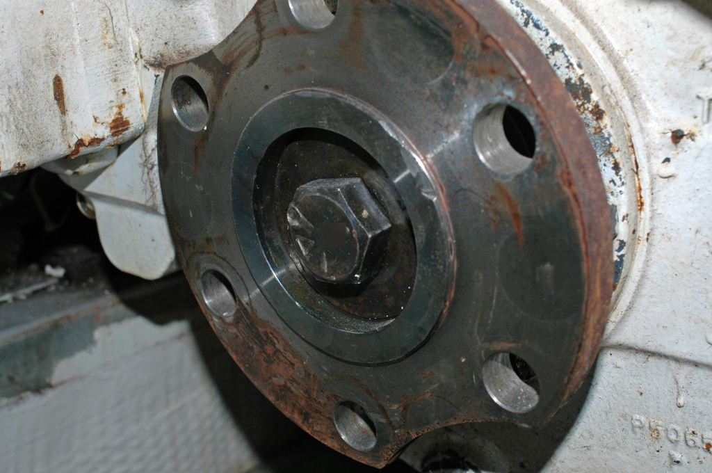
Step 15: Once the adjustment process is complete, and the gap is minimized, the coupling bolts should be installed. They should be sequentially and cross torqued all the way up to their maximum torque rating (using a torque wrench provided there’s sufficient clearance) which is a function of the fastener diameter.
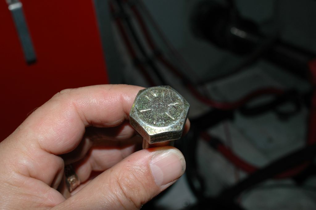
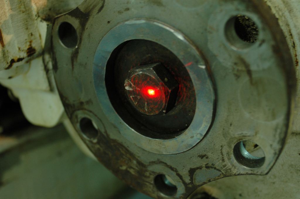
Step 16: Fasteners used with couplings should be grade 8 mild steel, denoted by six radial dashes on the head, 60° apart. Under no circumstances should stainless steel bolts be used. Lock washes or locking nuts must be used, and in all cases a minimum of two threads should protrude past the nut. Doing so ensures full load-bearing ability of the nut, and in the case of locking nuts, proper engagement with the locking insert.
Step 17: Once fasteners are installed and torqued, they, and steel couplings, should be painted or otherwise corrosion inhibited, as mild steel of this sort is prone to rapid rusting. Do not apply thread anti-seize compounds to alignment related threads, including motor mount studs and coupling fasteners.
Step 18: Ideally, when the alignment is complete, none of the motor mount adjustable screw studs will be at the full extent of their travel, fully up or down; instead, they should be closer to the middle of their travel. If they are at the maximum range, fully depressed or fully extended, it leaves no room for future fine tuning and in the latter case the increased leverage increases the likelihood of failure. In some cases, mounts may require the installation of shims (acceptable shim material includes aluminum, steel and fiberglass sheet, but never UHMW polymer, also known as King Starboard®) to offset overextension of the mount’s studs, while in other cases brackets or stringers may require modification to lower an adjustable mount either to improve exposed stud length or to complete alignment.
Step 19: As an optional final measure of proper engine alignment, and more specifically the interface between the shaft and coupling, and coupling faces and pilot bushing, a dial indicator can be used to measure shaft irregularity or “run out”. Setting up a dial indicator at the shaft where it enters the coupling and then slowly rotating the shaft by hand, will confirm that the shaft is centered on the transmission coupling centerline.
Step 20: Once complete, the vessel should be sea-trialed, after which the torque of all fasteners related to alignment should be checked and ensure al are adequately corrosion inhibited. Consider applying a fastener witness product such as Torque Seal, to alert users and service personnel to fasteners that have loosened.

