
From the Masthead 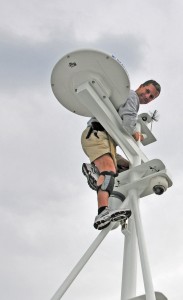


The Ins and Outs of Engine and Shaft Alignment
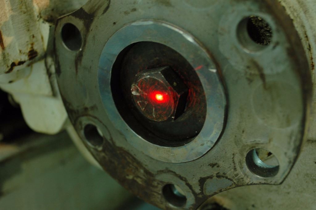
A laser can be used to “sight through” a shaft. Here the laser has been positioned in the aft-most shaft bearing, and aimed at the transmission output coupling. When it’s centered, the shaft droop will have been eliminated. The pilot bushing is damaged, dents can be seen between the 12:00 and 2:00 o’clock position.
Engine and propeller shaft alignment are among the most critical aspects of propulsion system installation, reliability and maintenance. Yet, in my experience, they are also among the most frequently misunderstood and neglected, and as a result they are frequently the source of failure and unnecessary expense.
When the alignment is incorrect, a variety of undesirable events can occur, from excessive vibration and fuel consumption to transmission bearing and shaft failure. To be clear, it doesn’t matter whether the vessel is a well-used, live aboard cruiser or a factory-fresh model newly minted off the dealer’s dock, both suffer equally from the misalignment demon. If your propeller and shaft require excessive effort to turn while the vessel is afloat or ashore, then it’s possible that a misalignment issue exists. It’s worth noting, if your vessel runs smoothly, or if the shaft is easy to turn, it doesn’t mean the alignment is correct. Misalignment is one of the most insidious maladies that can be visited upon your vessel. Therefore, you should take no chances, make sure yours is correct. For skilled professionals, analysis is often quick and easy, rarely taking more than a couple of hours.
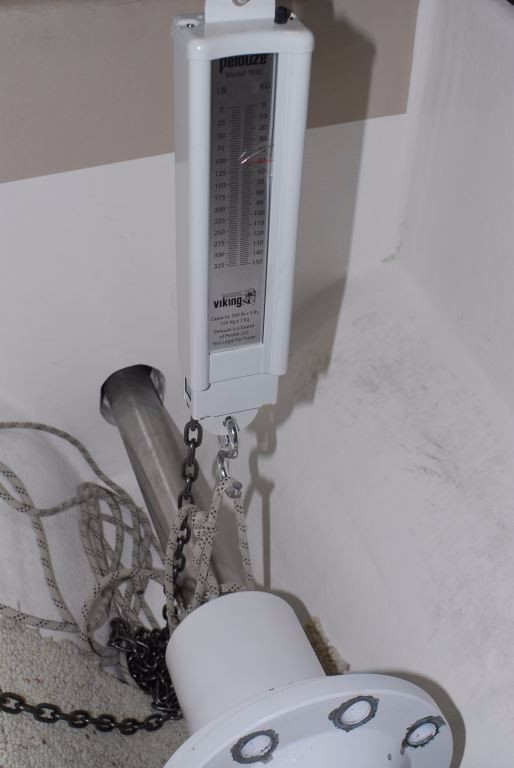
Eliminating shaft droop can be accomplished using a hanging or conventional scale, thereby accounting for the weight of the shaft and coupling.
Engine vs. Shaft
It’s important to make the distinction between the two different types of alignment that exist aboard virtually every vessel. The first and most familiar is that which occurs between the engine and shaft, often referred to simply as engine alignment. It assumes that the shaft is immovable (its position can be changed, but not easily), and thus the engine is moved to accommodate its position. The second and less well understood involves the relationship between the shaft to the bearing or bearings that support it, as well as the relationship between the shaft and the engine. Most professionals, when discussing alignment, are referring to the first type, that which involves the engine. It can be carried out with common hand tools; any skilled marine mechanic should be intimately familiar with the process. Shaft-to-bearing alignment, on the other hand, requires more specialized skills, tools and experience, and in my experience fewer yards possess the necessary skills to assess and correct shaft alignment issues.
Engine Alignment
For engine alignment, the primary area of concern is the interface between the transmission output coupling and the shaft coupling. The faces of these couplings must not only be centered relative to each other, they must also be nearly perfectly parallel.
Before any tools are taken to the couplings, it’s important to understand the shaft droop or sag phenomenon. Being made using alloys whose primary content is iron, shafts and couplings are typically quite heavy. Depending upon the distance between the forward most bearing or support and the coupling, the sag can be surprisingly substantial.
When I’ve discussed this issue with some mechanics they’ve expressed skepticism, ‘How could a two inch diameter steel shaft sag?’ they asked. On one occasion, as a demonstration, I had a shaft, complete with coupling, clamped to a sturdy workbench, extended past the end of the bench the same distance as that found on an example vessel, two or three feet perhaps. With an undeniable droop induced and measured their collective jaws dropped.
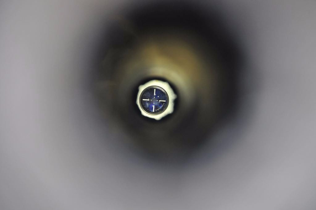

Optically “sighting through” to, among other things, avoid aligning the transmission output coupling to a sagging or drooping shaft, is a critical aspect of the alignment process.
Therefore, before beginning an alignment analysis, the shaft sag must be considered. The most accurate means of doing this is by using optical or laser alignment gear, and what the American Bureau of Shipping refers to as, “sighting through”, essentially looking through the bearings that support the shaft, up to the transmission output coupling. Alternatively, the free hanging weight of the shaft of the and the coupling (that is half the calculated weight of the free-hanging shaft section, and the full weight of the coupling) can be calculated and accounted for with upward force, using a conventional or hanging scale.
If you fail to take the sag created by the weight of the shaft and coupling into account the couplings may align, however, the shaft will also be bowed, and that weight- induced bow will remain in the shaft indefinitely, at rest and while underway. Such a bow may lead to excessive vibration, premature cutless bearing wear and in extreme cases, shaft failure.
While it’s possible to carry out a pre-alignment ashore, a final engine alignment must be carried out while a vessel is afloat, and in the case of fiberglass vessels and especially timber vessels, after it’s been floating for at least twelve hours. Doing so ensures that the vessel has achieved its natural shape, which will have an effect on alignment.
Hands On
Begin by inspecting the motor mounts sometimes referred to in industry argot as “isolators”. Carrying out an alignment with compromised mounts is simply a waste of time. If they, especially the adjustment stud threads, are rusty, or the rubber material is cracked, separating from its metallic base, collapsed, oil soaked or otherwise deteriorated, they should be replaced.
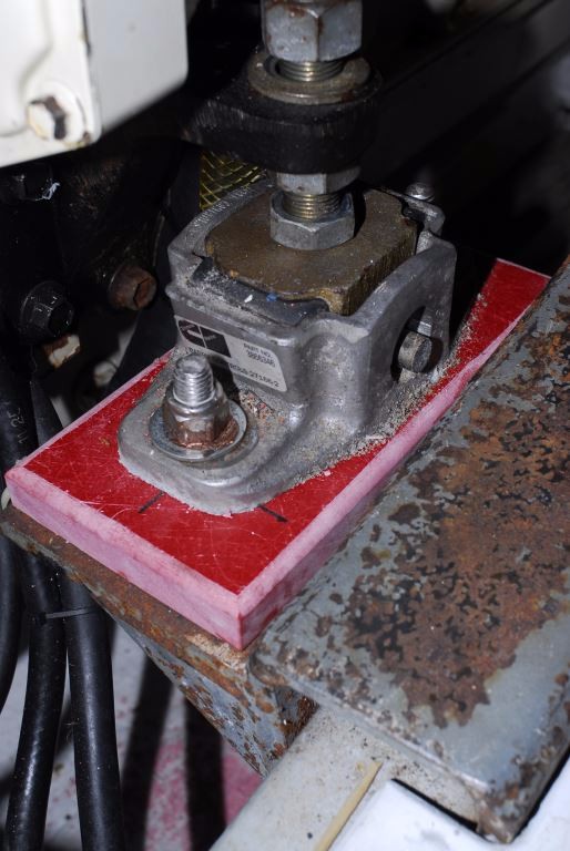
Motor mounts carry out a Herculean task, supporting the engine and absorbing both vibration and thrust, however, they are the primary means of adjustment for alignment. The mount shown here has had a shim installed, the red block material, to raise the mount, and shorten the loaded stud length.
Next, remove the coupling bolts and separate the two couplings. Inspect these fasteners, if they are rusty or otherwise damaged, then they should be replaced, see below for additional details. Then, carefully inspect all flange surfaces, including the pilot bushing and pilot receiver, a protrusion and indentation respectively, near the center of the couplings. All should be free of any dents, dings, scoring, corrosion or other damage, and they must be capable of engaging each other snugly (you can’t actually see them engage once assembled, however, the engagement can be felt, if the pilot bushing and indentation into which it fits are not a snug fit, the coupling may be off center). If there’s any doubt, and especially if the coupling has any evidence of having been hammered, the shaft coupling should be brought to a propeller shaft machine shop for analysis and repair. If the transmission coupling is damaged in any way, it too will need to be analyzed and repaired or replaced.
Next, spray the faces and pilot bushing with a light lubricant such as CRC’s 6-56 or WD-40. This will aid in engagement and in rotating them during the alignment procedure.
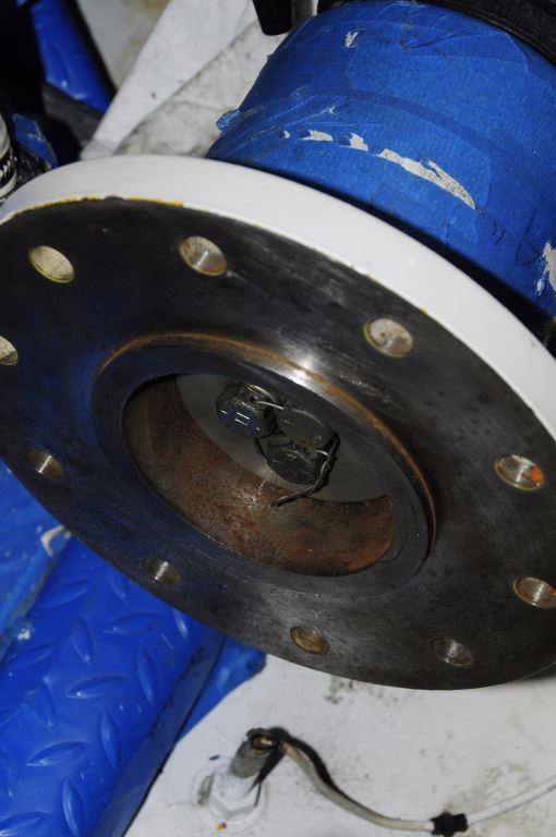
The pilot bushing, the protruding ring within the coupling face, shown here, ensures that the two couplings are centered on each other. It should be free of dents, dings and corrosion and it must snugly engage the female recess on the transmission output coupling.
Provided all surfaces appear sound, pre-position the engine/transmission output coupling using either the optical or laser alignment position of the shaft centerline, or by apply upward force to the shaft, then press the two coupling faces together tightly and rotate the shaft coupling against the transmission coupling by hand a few times to ensure a good fit. Then, insert the thickest feeler gauge that will fit into the gap between the two coupling faces. A maximum of approximately 0.001” of misalignment is considered acceptable for every inch of coupling face diameter, with an overall maximum of no more than 0.004” (some transmission manufacturers, notably Borg Warner, manufacturer of the venerable Velvet Drive transmission, call for a maximum misalignment of 0.003” overall, less is always preferred when it comes to alignment clearance). Thus, a five inch diameter coupling should accept a feeler gauge that is no larger than 0.004” (again, less is better) at any point around the interface. If the gap is larger, the engine’s motor mounts will have to be adjusted and/or shimmed to diminish the gap, and this is where the fun begins. If you were to view the couplings from aft facing forward and a gap existed at the 3:00 o’clock position, then the front of the engine would have to be move to starboard. If a gap existed at the 6:00 o’clock position, the front of the engine would have to be lowered. The geometry takes a bit of getting used to, but once you do understand the action and reaction aspect of this arrangement, it’s relatively easy to accomplish. Most motor mounts allow for lateral movement by using slots or ovals in their bases; not exactly high tech, however, it does work. Moving the engine from side to side can be a bit challenging, depending upon its size and weight, for larger engines a hydraulic jack may be required, while a simple lever, a 2×4 for instance, can be used for smaller engines. Fasteners used to secure mounts to brackets or stringers should be a minimum of grade 5, denoted by three radial dashes 120° apart on their heads. Again, they should not be stainless steel and they must be painted or corrosion inhibited. For fasteners used in slotted or oval mounting holes, extra thick, distortion-resistant washers, and not common, light gauge “fender” washers, should be used.
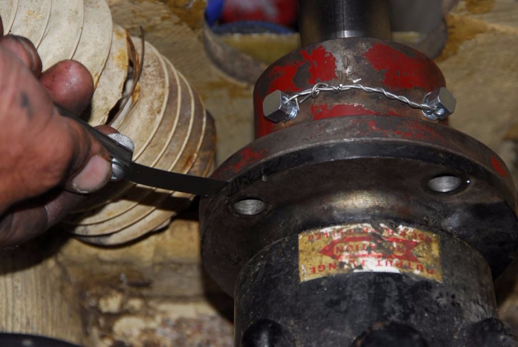
Tried and true, using feeler gauges to measure and close the gap between propeller shaft and transmission output couplings.
Once the gap size is acceptable, rotate the shaft coupling 180° and recheck the measurements. If any change occurs, the coupling, shaft or fit between the two is not true, in which case they will need to be removed and taken to a shaft shop for inspection, and a process known as ‘fitting and facing’, wherein the coupling, while fit to the shaft, is machined on a lathe to ensure its face is perpendicular with the shaft’s centerline. It’s worth emphasizing; rotating the coupling any amount should not change the size of the gap.
Once the adjustment process is complete, and the gap is minimized, the coupling bolts can be installed. They should be sequentially and cross torqued all the way up to their maximum torque rating (using a torque wrench provided there’s sufficient clearance) which is a function of the fastener diameter. Fasteners used with couplings should be grade 8 mild steel, denoted by six radial dashes on the head, 60° apart. Under no circumstances should stainless steel bolts be used. Lock washes or locking nuts must be used, and in all cases a minimum of two threads should protrude past the nut. Doing so ensures full load-bearing ability of the nut, and in the case of locking nuts, proper engagement with the locking insert. Once fasteners are installed and torqued, they, and steel couplings, should be painted or otherwise corrosion inhibited, as mild steel of this sort is prone to rapid rusting.
Ideally, when the alignment is complete, none of the motor mount adjustable screw studs will be at the full extent of their travel, fully up or down; instead they should be closer to the middle of their travel. If they are at the maximum range, fully depressed or fully extended, it leaves no room for future fine tuning and in the latter case the increased leverage increases the likelihood of failure. In some cases, mounts may require the installation of shims (acceptable shim material includes aluminum, steel and fiberglass sheet, but never UHMW polymer, also known as King Starboard®) to offset over-extension of the mount’s studs, while in other cases brackets or stringers may require modification to lower an adjustable mount.
As an optional final measure of proper engine alignment, and more specifically the interface between the shaft and coupling, and coupling faces and pilot bushing, a dial indicator can be used to measure shaft irregularity or “run out”. Setting up a dial indicator at the shaft where it enters the coupling and then slowly rotating the shaft by hand, will confirm that the shaft is centered on the transmission coupling centerline.
Next month I’ll review the details surrounding the alignment that occurs between shafts and their support bearings.
To read Part II, please follow this link.

