
Text and photos by Steve D’Antonio
Copyright © 2016
From the Masthead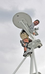
A few days ago I completed an article for a boating magazine, in which I offered advice for those attending upcoming boat shows, covering, among other things, the standards to which boats are built. Doing so reminded me of the importance of this subject, and just how much misunderstanding surrounds it.
In a discussion with a client recently, regarding an inspection I carried out aboard his four year old vessel, he said, “I’m surprised at the number of electrical faults, nearly all of which seem to have been there from the start. What were the standards when it was built?” In a world where so much is governed by standards, automobiles, aviation, building construction and commercial shipping, my response no doubt came as a surprise to him, as it does to so many boat owners, “There were no [electrical] standards in effect when the vessel was built, and there are none today, at least none that US boat builders, and repair yards, are required to follow by law”. Where construction details are concerned, specifically electrical, fuel and ventilation systems, only gasoline-powered vessels are required to meet a set of guidelines, laws if you will, set forth in the US Code of Federal Regulations. With the exception of those governing navigation lights, fire extinguishers and a few others, recreational, diesel-powered vessels are exempt from these requirements.
Therefore, the onus is on boat builders and boat yards to follow voluntary standards, which include those established by the American Boat and Yacht Council (ABYC). Hardly a day goes by where I don’t look up, cite, recommend or reference one of these standards, contained in the voluminous, ‘Standards and Technical Information Reports for Small Craft’. The value of these standards, and the manner in which they’ve raised the quality, reliability and safety bars within the marine industry, cannot be over stated. There’s more to the story, however; so I’ll alert readers when the full article is published and available on line.
For now, here’s a preview. What does this mean for a boat buyer, new or used? If you are considering a new boat, be certain to ask the broker if the builder belongs to ABYC (you can confirm membership on ABYC’s website), and if so, does the vessel comply with ABYC Standards, and if so, which ones? There are over 60. It’s rare to encounter a builder today who is not a member of ABYC, but if you do it’s cause for concern. If the builder indicates compliance with some or all relevant ABYC Standards, confirm this with a pre-purchase survey before closing the deal. Yes, even new boats should be inspected. For used vessels, its condition should be evaluated on several levels, including ABYC compliance. I often hear sellers say, “It met the standards when it was built, why does it need to meet current standards?” The simple answer is, a short circuit, fire, carbon monoxide leak, electrocution hazard or fuel leak can’t read the standards, it doesn’t matter what was acceptable at the time of construction, if it’s unsafe, it’s unsafe. Finally, anyone carrying out work on your vessel, service, repairs or modifications, new or used, should agree to do so in compliance with current ABYC standards (http://www.abycinc.org)
This month’s Marine Systems Excellence eMagazine feature, part two of a two part series, continues our look at running gear alignment. I hope you find it both useful and interesting.
The Ins and Outs of Shaft Alignment – Part II
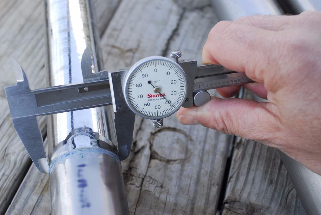
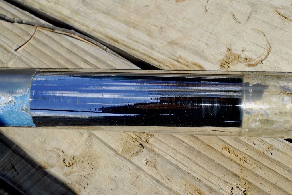
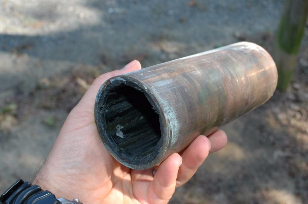
Bearing misalignment can lead to both bearing and shaft wear. The maximum tolerance for shaft wear is just one thousandth of an inch. The shaft shown here has been condemned as a result of excessive wear, caused by gross misalignment.
In last month’s column I reviewed the importance of, and techniques for, ensuring proper engine alignment. That is, the alignment between the engine and the propeller shaft. In the second and final part of this series we’ll review shaft alignment.
Nearly all marine engines are designed to be adjustable, to a point, relative to the propeller shaft, using adjustment or jacking nuts on their motor mounts. The adjustment should be thought of as no more than fine tuning, the maximum range of vertical travel being limited to no more than an inch or two at the most, which is considerable when one considers that alignment is typically measured to just a few one thousandths of an inch. Thus, the responsibility rests with the naval architect and boat builder to ensure that the design and execution of the engine installation guarantees near perfect alignment with the shaft before the motor mounts are adjusted.
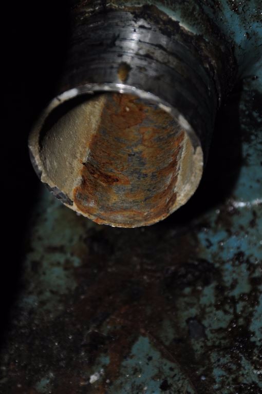
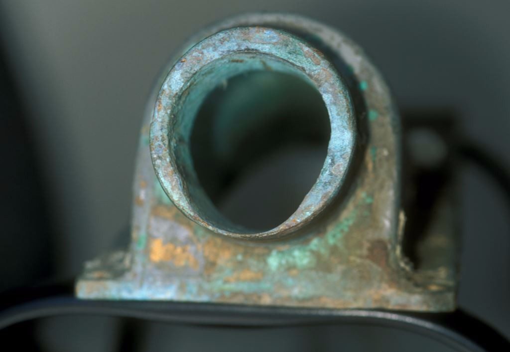
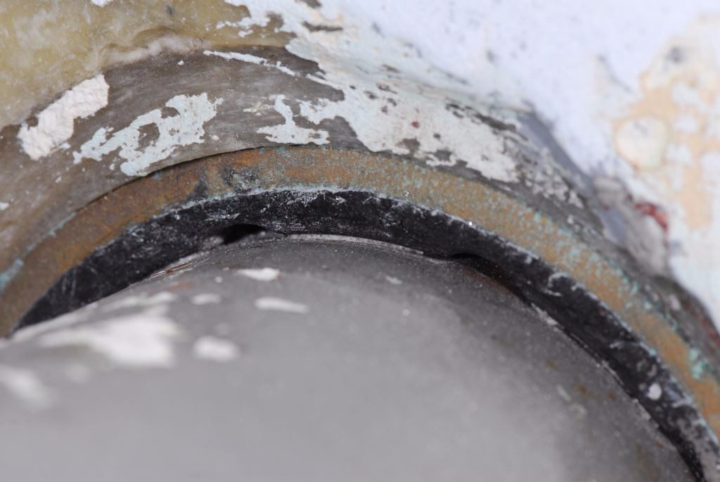
These shaft logs show signs of wear caused by improper shaft alignment. Contact of this sort can lead to increased fuel consumption, vibration, heat generation and eventually flooding.
The Other Alignment
There is another side to the alignment story; it involves the support and position of the propeller shaft relative to its bearing(s), the shaft log and the engine. While engine alignment is, or is expected to be, well understood by most marine industry professionals, shaft alignment is, on the other hand, far more esoteric and well understood by fewer folks in the industry. In my experience, precious few truly understand its importance, and the consequences of misalignment, and fewer still understand the techniques and processes involved in making adjustments and corrections.
Interestingly, and contrary to popular belief, shaft misalignment rarely leads to vibration, as the bow or offset induced in a shaft by misaligned bearings is constant. If, on the other hand, as a result of misalignment, the shaft makes contact with the shaft log, more on what that is in a moment, it may lead to vibration. Improper shaft alignment can lead to excessive shaft drag, and the resultant increase in fuel consumption, and accelerated bearing and shaft wear.
A few years ago I inspected a vessel while it was hauled out. When I came to the propeller I made an unsuccessful attempt to rotate it, to gauge the condition of the bearings and alignment. Regardless of how hard I tried, I was unable to rotate either shaft on this twin screw vessel 60 foot vessel. This is a clear indication of either severe shaft misalignment (as opposed to engine misalignment, which rarely imparts this sort of resistance) or, less commonly, swollen shaft bearings. While final alignment of an engine to its shaft should only be carried out while a vessel has been afloat for some time, even when hauled out the shaft should turn without undue effort once adhesion between it and its bearings is broken. In this case, even when hanging on a propeller blade I was unable to budge these shafts. Clearly, this vessel was in need of a shaft and bearing alignment analysis.
Misalignment can make shafts difficult to turn, however, so too can swollen bearings. That possibility should be explored as part of any analysis of a shaft that is difficult to turn.
How Shaft Bearings Work and are Supported
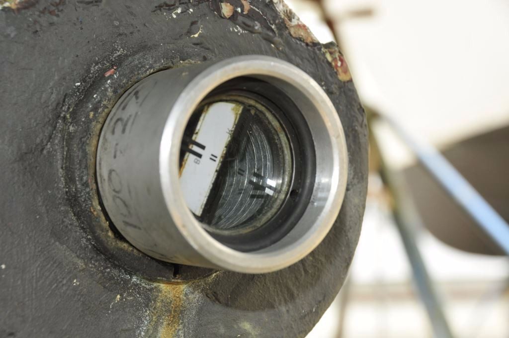
In virtually all cases, propeller shafts are supported by one and sometimes as many as four, for longer shafts, bearings, often referred to by their trade name ‘Cutless® bearings’. Shaft bearings are tubular pipe-like components, the outer shell of which is typically made of brass, and sometimes a fiberglass-like material (the latter is designed to be used on steel and aluminum vessels, to avoid the corrosion potential caused by copper alloys like brass), with an inner liner of grooved or fluted rubber. It comes as a surprise to many users that the sole source of lubrication and cooling is seawater; if water flow to the bearing is insufficient or if it’s interrupted by marine growth on the shaft or clogging of a shaft log water injection system, rapid bearing wear can ensue.
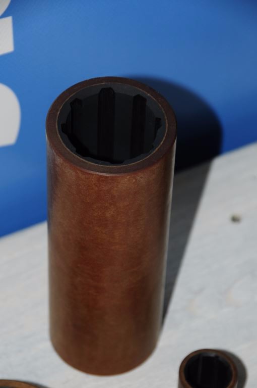
Shaft bearing shells are typically made of brass (above), however, non-metallic versions (top), are available, which are often used in steel and aluminum struts to avoid galvanic corrosion.
Shaft bearings may be found in and supported by struts, I or V shaped metal supports attached to the vessel’s hull, through which the shaft passes, and/or embedded within the shaft log, in the keel or hull. When the vessel is built, the builder must make a concerted effort to ensure that bearings are properly located to support the shaft, while ensuring that they are also aligned with the theoretical shaft’s centerline, a line that is perpendicular with, and begins at the center of, the transmission output coupling, and travels aft through the bearing(s). The line must also be centered in and parallel with the bearing(s). If the builder is successful in ensuring this alignment, barring groundings or other damage, it should remain correct throughout the life of the vessel. While small adjustments may be made to the relationship between the engine and shaft, by adjusting the location of the former, the shaft’s relationship to and alignment with the bearings should remain constant.
Analysis and Adjustment
In practice, it’s not uncommon to encounter shafts and bearings that are misaligned, and the greater the number of bearings, the greater the likelihood of misalignment. While shaft to bearing alignment can be challenging, aligning a shaft to several bearings, as well as the general location of the engine, can be daunting. As such, it’s easy to see how this process can go awry while the vessel is being built.
Traditionally, during construction or repairs, the process begins with a length of small diameter yet stout string or wire, which is glued to the center of the transmission output coupling. It is led aft, through the hole through which the shaft passes, the shaft log, and out the vessel’s stern section, where it is anchored, typically to a weighted object like a jack stand. Using this string or wire as a reference point, bearings and, if present, struts are positioned. When properly aligned, the bearing(s) must remain centered on and parallel with the string or wire.
While this traditional approach is still used, more modern tools are now routinely employed; these include lasers and optical sights, both of which were mentioned last month. Using a laser or sighting tool, an installer can, with a great accuracy, position one or more bearings along the sight line. While this aspect of shaft alignment is critical, it’s the easy part. Setting the bearings in place, permanently, can be more challenging.
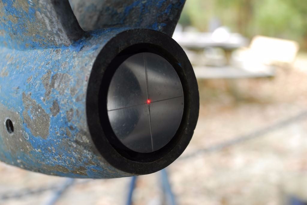
Bearing alignment can be analyzed using either optical (top) or laser (above) sighing equipment. This alignment method eliminates the need for string or wire and caliper measurements.
Initially, the strut or bearing is “dry fit”. That is, it’s positioned roughly to determine what needs to be done to align it with the shaft. The process typically involves a technique known as casting. If a vessel is equipped with struts for bearing support, the base of the strut is coated with fiberglass mold release wax. It is then set into a mixture of thickened, reinforced epoxy and positioned so that it remains centered on and parallel with the string, laser or optical sight or shaft line. The strut is “hung” from support fasteners and wedges are used to adjust its height and orientation to the shaft centerline. Once the position is set, the epoxy is allowed to cure, after which, thanks to the mold release wax, the strut is removed. Wax is removed from the strut and the epoxy surface, and the strut is then set in polyurethane bedding compound, ensuring a watertight seal with the hull. In some cases, the bearing centerline may be below that of the shaft. In this instance, depending on the degree of misalignment involved, a recess may have to be made in the hull, to accept the strut’s base, the strut may require modification or a new strut may need to be manufactured all together.
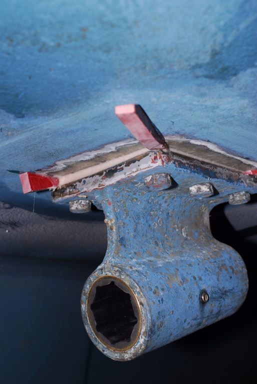
Struts are typically repositioned, to achieve proper alignment, using thickened epoxy as a shim. Wedges are temporarily inserted to adjust placement.
A similar process is employed for bearings that reside within the shaft log, and strut. The bearing itself is waxed and set in epoxy; wedges are used to position it so that it remains parallel with and centered on the shaft line until the epoxy cures. All bearings should be a light press fit in the shaft log or strut. Ultimately, bearings are retained using set screws, a minimum of two must be used, they should be installed at 60° to each side of the bottom centerline, or at the 4 o’clock and 8 o’clock positions (alternately, they may be installed at the 3 and 9 o’clock positions, but not above the propeller shaft centerline). Set screws must be harder and galvanically noble to the bearing shell; indentations (not holes) should be drilled into the bearing shell, using a drill bit whose tip angle matches that of the set screw, which the set screws engage. A thread locking compound should be used on set screw threads.
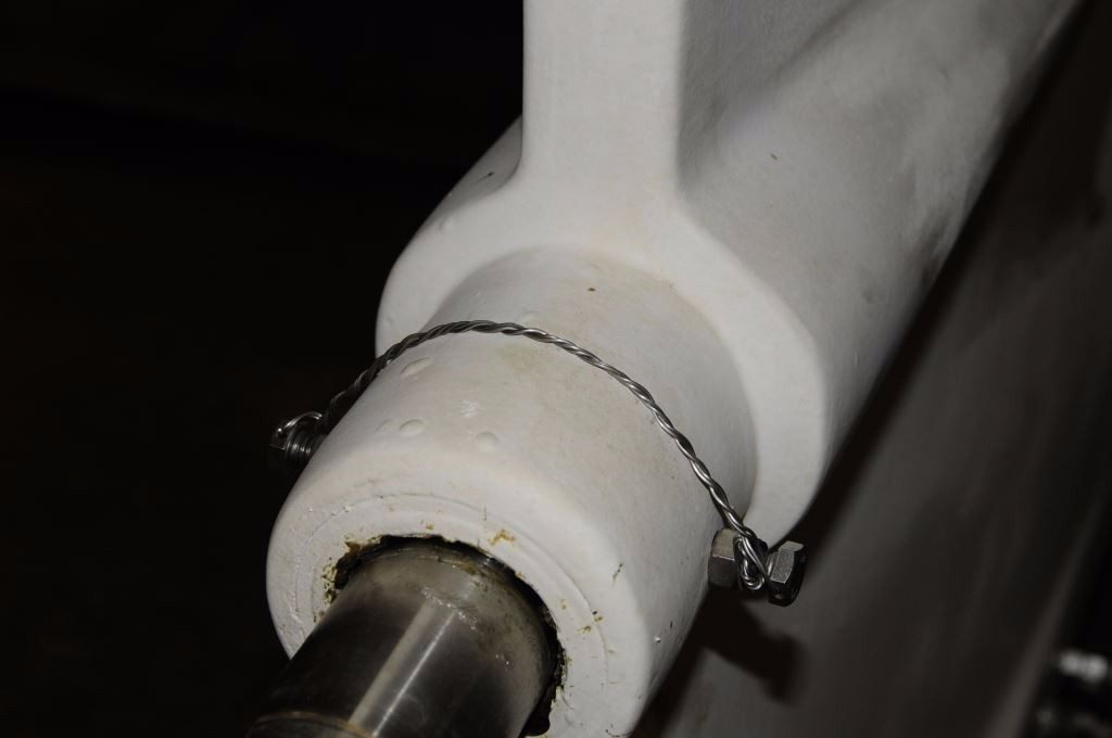
Shaft bearings must be retained with set screws. Here, two screws , retained with seizing wire, are installed at the three and nine o’clock positions.
Ultimately, once the shaft to bearing alignment is complete, even a large diameter, long shaft should, with the benefit of nothing more than light lubrication from soapy water, rotate with little more effort than is required to lift an overhead garage door.
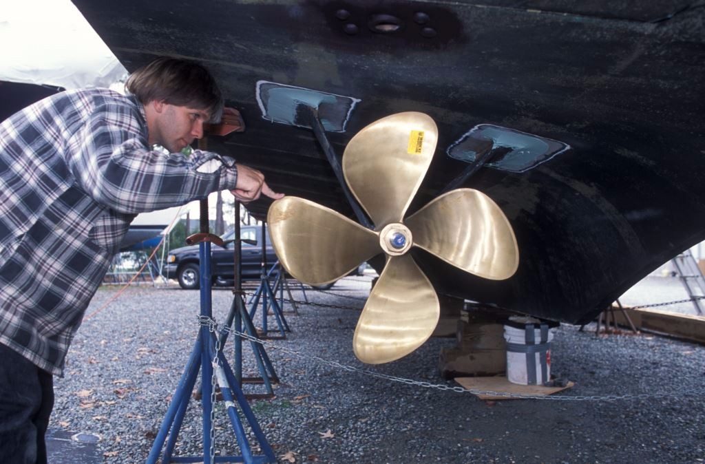
When properly aligned, propellers and shafts should turn with relative ease.
Before entrusting your vessel to anyone for shaft alignment analysis or adjustment, carefully scrutinize their knowledge and experience on this all too important, yet frequently misunderstood, subject, and ask for references as well.

