
Photo Essay: Not a Cord Grip
These are small, inexpensive, and readily available parts, and they are critically important; without them the worst-case result can be fire and/or electrocution, and best case may be simply a component failure.
Cord grips are used for two purposes. The first is to immobilize a wire or cable where it passes through an enclosure, so that tension placed on the wire does not transmit strain to electrical connections. The second is to prevent chafe of that wire where it passes through an enclosure.
Proper cord grips, sometimes called strain relief connectors, achieve these two goals. However, in many cases they are not properly sized to engage the cable they are tasked with supporting. In the example shown here, the cord grip is designed to be used with a far larger cable, and one with a round rather than flat construction. Ultimately, you know if a cord grip is doing its job if you pull on the cable, and there is no movement relative to the grip. The one saving grace in this case is, it’s serving a chafe protection.
Ask Steve
Greetings Steve,
First of all, thank you for your continued contributions to the community. I literally get smarter every day from your emails, articles, and postings.
Bottom Line: I want to PROPERLY install a crash pump in place of a manual pump (bilge).
I have an Edson manual bilge pump on a Nordhavn 40, as installed from the factory. For our use case with 2 persons on board, there is virtually no chance there will be a free hand in an emergency to use this pump. We will be fully immersed in damage control, communicating, and navigating should we be taking on water.
I would like to remove the Edson and install a submersible trash pump in the lower bilge behind the engine, but high enough to keep it dry. I would use the existing hose and seacock from the removed Edson. This 120VAC pump would be sized to start on our inverter. The submersible trash pump is appealing as it is salt water rated, tolerant of debris, NOT GASOLINE, and can be left energized on a float switch. I have suitable power available
My concern is water entering the bilge from the open seacock. Presently there is no device between the Edson pump and the seacock. The Edson pump is above water level, while the submersible pump would be below.
Thank you for your consideration!
Jeff Petty
Jeff:
The safest route approach for this pump retrofit would involve installing an anti-siphon valve, so that if the discharge becomes submerged, a siphon can’t be established between the ocean and your bilge.
In most cases, anti-siphon valves must be installed a minimum of 12-inches above the dynamic or healed waterline, i.e. the waterline if the vessel is heeling (and aground for instance), and in some cases as much as 18-inches. That anti-siphon valve should, like all anti-siphon valves, be serviced annually. More on anti-siphon valves here.
The Edson pump does have built in dual duck bill check valves, so in theory, as long as those are intact, water could not flow in the wrong direction, back into the vessel.
On your vessel, that may require the anti-siphon valve to be installed in a saloon settee.
Because this pump will be submerged, and AC-powered, I also recommend it be supplied via a GFCI outlet.
Dear Steve,
Our Nordic Tug 39 was recently hauled at the marina. I noted an excessive amount of anode corrosion on the 4 Sidepower Anodes as well as on the Divers Dream anode on the stern. The rudder anodes were about normal, having owned the boat for 5 years. The Sidepower anodes were all but gone. Usually, we would have about 2/3 of each one remaining. All anodes are changed out before launch. The Sidepower Thrusters are not bonded to the boat, the rudder is however.
The only changes made this year over the past years is the replacement of the house and start batteries. Same brand / size replaced them. The positive connections on the house batteries (there were 7}, have been moved to a bus bar near the batteries. Work was done by an ABYC Technician at Front Street Shipyard.
I have reviewed your articles, IT ATE MY ZINCS, August 2019 Cruising World, and A NOD TO ANODES, October 2019 as well reviewed Nigel Caldor’s Boatowner’s Mechanical and Electrical Manual, 4th edition, pages 260 – 287. You suggest the use of galvanic isolator. Nigel Caldor suggests the use of an ELCI device. Our boat does have an ELCI made by Blue Sea Systems on both of the 30-amp power cords.
The boat yard has tested the slip and dock we are at. They could find no problem and suggest the problem may lie within our vessel on the 12-volt side. We use one 30 amp cord when we are on the boat. When we leave for the week, we turn off the Circuit Breaker, but we do not unplug the boat. Nothing is left running on the boat other than the “emergency” circuits, bilge pumps etc.
My conundrum is where do we start. Should we add a galvanic isolator prior to the ELCI device? Do the symptoms point to our vessel as the culprit? Are there any tests that can / should be run prior to launch that could help identify the problem.
Many thanks for your insights.
Barry Shapiro
Barry:
You said the boat yard “tested the slip and dock”, do you know exactly what they tested and was the test carried out by an ABYC Certified Corrosion Technician?
ELCI’s have no bearing what so ever on corrosion, they are solely designed to prevent AC current leakage, and the potential for electric shock drowning, more on that here
Every vessel that has shore power should be equipped with a galvanic isolator. Without one, whenever you plug into shore power, your vessel’s bonded underwater metals are potentially connected to the underwater metals of vessels around you. If those vessels’ anodes are depleted, it’s possible for your anodes to protect them as well as you, albeit at a more rapid rate of consumption. More on galvanic isolators here.
I can’t say why your thruster anodes have been consumed more rapidly, if they are truly isolated then they should not be affected by nearby vessels, or the lack of a galvanic isolator. Their protection level can be checked with a reference cell test, see below.
My recommendation is to start by installing an ABYC compliant galvanic isolator, and then have a corrosion survey and reference cell test performed by an ABYC Certified Corrosion Technician. Without that test, any conclusions are purely speculation, and a case of guess, check and hope for the best, an approach that should be avoided, especially where corrosion analysis is concerned.
You might also find these articles of interest…
Steve,
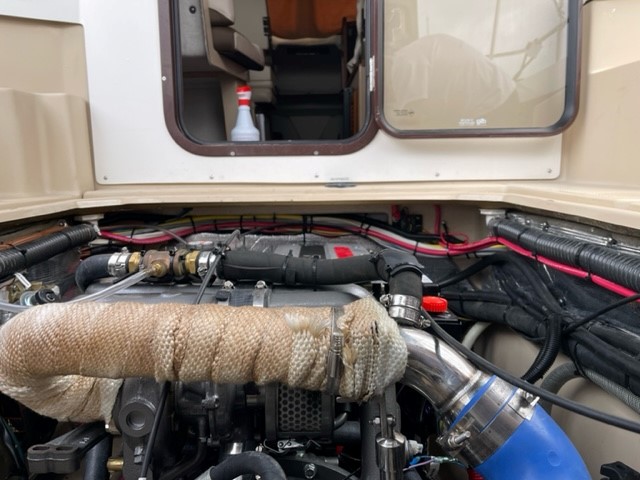
I am looking for help and advice on my boat’s newly installed exhaust system. This year I had my 25’ Ranger Tug re-powered and I am concerned about the placement of the mixing elbow water injection. See picture. Looking at the picture, it appears to me that the design is marginal and there is a possibility of water backing up into the turbo.
I would suspect while the engine is running that the exhaust system would work fine. However, when starting or stopping the engine if there is any water in the upper elbow and the boat is listing to port or rocking water could enter the turbo.
Thanks for your review.
Richard Clagett
Richard:
Based on the photo alone, which is not necessarily definitive, the down angle of the mixing nozzle does not look abnormal. Many engine manufacturers specify a required minimum angle where water is injected into the exhaust gas stream, John Deere’s is 25 degrees, Cummins’ is 15 degrees. I’m not certain if Yanmar provides such a specification, however, if they do then using a digital level I’d confirm this installation meets that requirement (and in the absence of a Yanmar spec, I’d say 15 deg. would be the minimum). Additionally, the highest point of the riser must be a minimum specified distance above the waterline, which again is specified by the engine manufacturer. There’s no way to know what that is from the photo, however, this should be checked. Again, my observation is purely anecdotal based on the photo.
There are four other observations worth sharing. The first, the insulation covering the dry exhaust section appears to be inadequate. At full throttle, under load, the surface of that insulation should not exceed 200 degrees Fahrenheit. I’d prefer to see a purpose-made insulation wrap or blanket that can be easily removed for inspection. More on exhaust system design, installation, and insulation, here.
The second, unless it’s beyond the frame, I do not see a wet exhaust temperature alarm sensor. These are typically strapped to the exhaust hose immediately after the mixing elbow, the blue silicone hose in your case. This is an ABYC requirement, it will alert you to a pending overheat scenario long before any damage occurs. More on those here.
The third, what looks like shift and throttle cables are routed close to, if not touching the exhaust. These cables should be routed away from the exhaust, especially the dry exhaust section.
The fourth, there is a bronze T installed in the raw water injection hose, laying on top of the engine, to which a clear PVC hose has been attached. I’m not certain what the clear hose is used for (stuffing box injection perhaps, or is it an anti-siphon device?), however, it is not rated for raw water applications.
Finally, in cases of repowers, my recommendation is that installers be tasked by having them to agree to all relevant ABYC Standards, as well as engine manufacturer installation requirements.

