
Text and photos © 2021 Steve D’Antonio Marine Consulting, Inc.
Photo Essay: Steering
Steering, it’s one of the primary systems you simply can’t do without, along with propulsion and watertight integrity. Without it, you are on the rocks, beam to, or making unintended contact with other vessels or immovable objects like docks and bulkheads.
Fortunately, most steering systems are relatively simple, and in the vast majority of cases failures are the result of either incorrect installation, or deferred maintenance; they are nearly always avoidable. An example of the former is shown here, my attention was drawn to it during a sea trial, when I noticed the ram base moving half an inch (12 mm) in either direction while doing S turns. Upon closer examination, it was determined that the fasteners used to support this ram were lag screws. While lag screws have their place, they should not be used for steering, motor mounts and other reciprocating loads, as these are most likely to induce loosening in all fasteners, especially those of the self-tapping variety. In addition to being the wrong type of fastener, these lag bolts were also undersized; the fastener’s shank should always match the size of the hole through which they pass; i.e. the hole must be “filled” by the fastener.
Steering components, rams, sheaves, and helms, should be secured using through-bolts, using self-locking nuts, or lock washers.
Ask Steve
Steve,
I have read with great interest your article about bonding systems to prevent corrosion.
As I experienced a severe, obviously DC stray current, corrosion problem in my 40 ft. mahogany yacht from 1957, I would like to hear your view of the cause and especially the potential problem with the aluminum bronze lead ballast bolts. I also hope this case is of interest to you as an example of the power of DC stray current.
The case is a follows: When the boat was lifted out of water in fall 2016 there was a white round area with a diameter of about 20 centimeters (8 inches, 200 mm) at the stern planking close to stern tube, which proved to be contaminated wood caused by electrical current (photo attached).
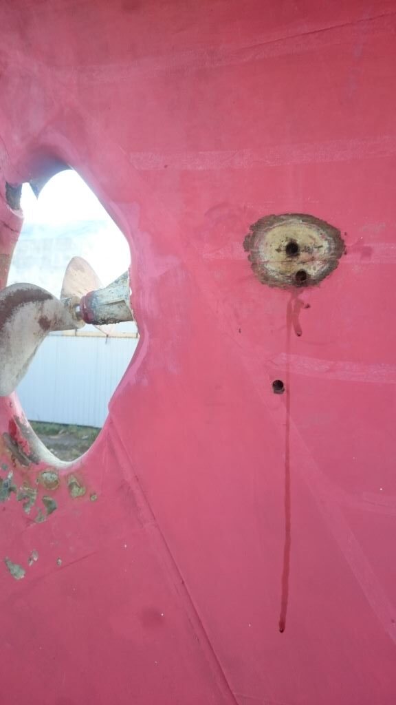
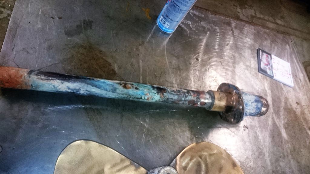
When I unscrewed one of the silicon bronze screws at that place, some water started running out of the hole. The tip of the screw was bright and a bit bended, it had been in direct contact with the bronze stern tube. I tested the stern tube for leaks, and it showed out that there was a hole in the stern tube at the place where there had been a contact with the screw. At the bronze propeller there was some pitting, or very small bubbles and underneath of those the bronze had turned to red copper. (Attached is a photo of the badly corroded stern tube after we took it out to replace with a new. You see also part of the propeller after it has been cleaned – no severe corrosion there.)
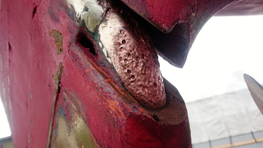
Severe damage had occurred at the 4-5 mm inch equivalent bronze plates that strengthen the rudder around the propeller opening. At the front edge closest to the propeller some 1 cm inch equivalent of the plate had totally disappeared and a wider area corroded (photo attached).
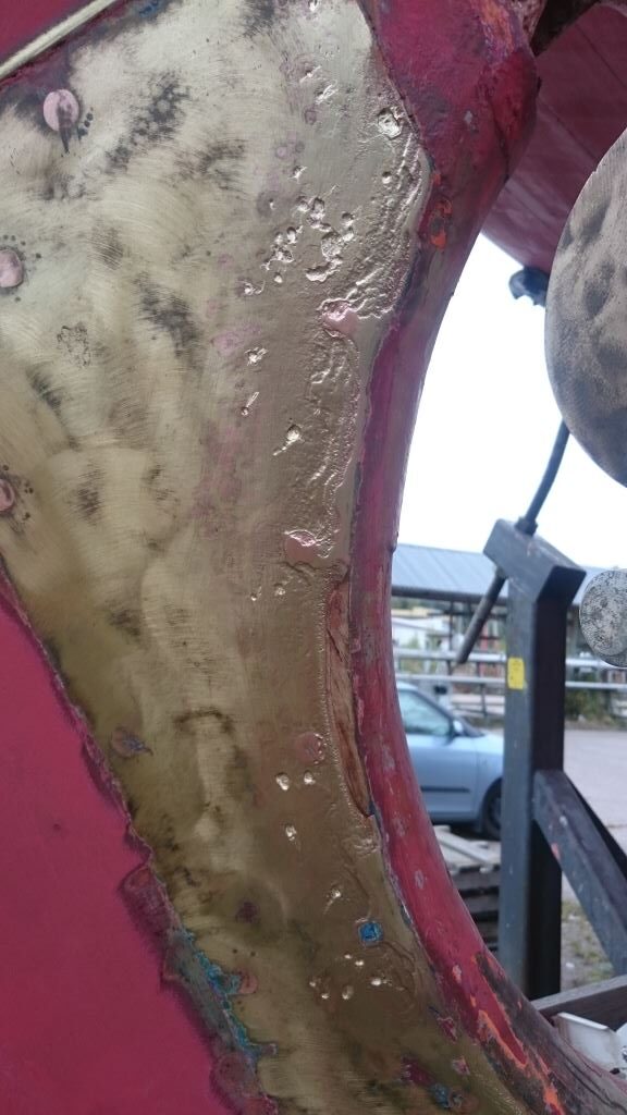
An even more severe damage was on the rudder shaft, at the bend where it turns inside the wooden rudder. The shaft material is called delta-metal containing 54-59 % of copper. 39-42 % of zinc. 1-1,5 5 of iron and 0,2-0,5 % of lead. In the picture attached I have cleaned that area and it shows the copper left when the other metals have corroded away. Fortunately the “wings” that turn the rudder higher on the shaft and the shaft itself outside that area were undamaged so this is not a structural problem. The corroded area does not go deep inside the shaft.
I had one zinc anode attached to the planking at stern with no electrical connection to any metal part (stupid!). It was almost as new.
I had the surveyor of the insurance company to check the cause. He first made a contact between the engine and the rudder shaft with thick cables. Here are the results of the survey:
1) There was no connection of the earth of shore power with the Volvo 2003 engine and metal parts of the yacht. This is OK.”
2) When shore power is connected, but the battery charger is not connected (battery voltage 12 V) there is a voltage of 0.3 V DC between the engine and the rudder. This is a small leak and can be taken care by zinc anodes connected the right way.
3) Shore power connected and battery charger on. There is a voltage of 0.75 V DC between the engine and the rudder. Battery voltage 13.7 V -the same as when running on the engine. This is a big problem. The Victron battery charger has plastic cover and is double insulated – no leaking of earth to the metal parts of the yacht.
The surveyor gave no further reason for the problem and still today I have no idea what was the cause of the leak. The shaft was directly connected to the engine with no flexible insulating joint between. There was one earthing wire of the Raytheon radar connected to the engine block (according to the instructions of Raytheon manual), but it was attached to a point high above the bilge water. The Rule bilge water pump was 11 years old. The pump wires had an extension protected by electric tape, (to be suspected), but this was located in the bilge at floor level, high above the bilge water. The bilge pump switch was of pneumatic type, with no electric parts in the bilge.
Today, there is a new stern tube installed, as well as a new shaft and bronze propeller and a new Nanni Kubota engine with a Vetus Bullflex flexible joint between the shaft and the engine. There is no earthing of radar to engine. I installed a new Johnson bilge pump with cables connected high above water level. New zincs are attached with electronic contact to the stainless steel stern tube and to the rudder bronze plates. There is also a zinc now on the propeller shaft in front of the propeller. So I think the stray current problem should not happen again.
Still, I have one worry. When taken out of the water then in 2016 and also in the fall last year I saw some signs of something leaking out between the lead keel and the wooden keel, at the places where some of the keel bolts (not all of the 10 bolts -long keel) closer to the end of the lead keel are located. The signs were not extensive, but out came some powdery- like white substance. I do not recall seeing that during the previous over 20 years I have owned the yacht. Now, the one inch keel bolts are of aluminum bronze with 9% of aluminum. I have studied a bit and have come across a thing called “selective phase corrosion” or “de-aluminization” where aluminum leaves the bronze metal and only fragile copper is left, which is a horrifying thing when keel bolts are concerned. The only way to make sure if there is a problem is to draw one keel bolt out. As this is quite a laborious and costly project I have not proceeded to it, but try first to find out if there really is a reason to suspect severe weakening of the keel bolts.
So, I would appreciate very much your opinion regarding the keel bolts and perhaps also some suggestions what to do to improve preventing of corrosion on my yacht.
King regards,
Jaakko Toiviainen
Jaakko:
Based on your description and the photos I have a few thoughts.
First, it is generally accepted, at least here in the States, that it is more harmful than helpful to bond a timber vessel. Bonding systems that are connected to anodes produce an alkaline solution at the cathode, the protected metal. I believe you alluded to some of that damage, and it’s shown in your photos. The process is known as delignification, wherein the lignin, the pulp between wood grain, is damaged by the alkaline. This can be accelerated by stray current, and it seems as if that’s what you’ve experienced.
The photos of the stern tube, and rudder plates indicate to my eye that these have a high zinc content, i.e. they are very yellow and thus appear to be brass rather than bronze. Because of its susceptibility to a process known as dezincification, brass (with a zinc content over 15%, less is preferred) should never be used in below the waterline applications. Thus, regardless of the presence of stray current or not, use of this alloy is problematic. For more on this subject see this article.
The ruder shaft corrosion, again because of its pink color, is indicative of dezincification. However, the aggressive pitting is also indicative of stray current corrosion. In addition to ensuring the vessel’s wiring is sound and free of obvious leaks into bilge or the surrounding water, there are several tests that should be carried out, the most important of which is a reference electrode test, more on that here. Using a silver silver-chloride reference cell, the protection level of various underwater metals can be tested. If they are bonded then the test would be conducted on the bonding system, otherwise they would be tested individually. Clearly the voltage measured between the engine and rudder is concerning, its source must be identified and stemmed.
If not already equipped, the vessel should have a galvanic isolator. While that will do nothing to prevent stray current corrosion, it will prevent nearby vessels from affecting the rate of consumption of your anodes.
As far as the keel bolts are concerned, it’s impossible to say what their condition may be without seeing them. In light of the other damage, and the residue you’ve noted, inspecting them is a reasonable and necessary course of action.
Finally, you may find this short article, explaining the details of both stray current and galvanic corrosion, useful.
Steve,
I read your water heater primer article and I have a question. My water heater is located above the level of my Perkins 4-108, so I am putting in a remote expansion tank. The Atlantic Marine water heater I have has the engine coolant “in” hose barb below the level of the engine coolant “out” hose barb. Where should I “tee” in my remote expansion tank hose? Into the hose to the engine coolant “in” line or the hose to the engine coolant “out” line (which is at a higher level than the coolant “in” line)? Or does it even matter as long as the remote expansion tank is at the highest level in the closed cooling system and the remote pressure cap is set at a pressure point lower that the cap on the main cooling expansion tank?
Thanks for any advice.
Michael Cox
Michael:
The purpose of the remote expansion tank is to allow air to be purged from the cooling system. Therefore, it should be T’d into the higher of the two hoses that are plumbed to the water heater’s heat exchanger, at the highest location in that hose, which presumably is where it is connected to the water heater.
The remote expansion tank’s cap pressure should be the same as the cap formerly used on the engine’s expansion tank (you can use the existing cap), and that cap, the new one for the engine’s expansion tank, should be replaced with one of a higher rating, so it essentially never vents.
(Question Cont.)
Steve,
I have another question related to the below question that you so kindly answered for me back in June of last year. The question is this:
I have a Perkins 4.108 (lowline with the expansion tank on the front of the engine over the thermostat). I would like to remove the expansion tank altogether since I will be plumping in a remote expansion tank with the pressure release taking place at the remote tank. The main reason is that the engine installation is really tight and it would allow me better access to maintain the fuel injectors, high pressure pump and started. There is a thermostat housing fitting which I have secured for the 4.108 that would allow me to connect a hose directly to the exhaust manifold and take the current stock expansion tank off altogether. Do you think this will work ok if I do it? The hot water heater is currently plumbed into the coolant side before the thermostat open up, should I put the remote expansion tank at the highest point on that side (before the thermostat opens) or at the highest point after the thermostat opens by teeing into the exhaust manifold coolant hose? The easiest would be to install by teeing into the water heater hose, but I am concerned about how I will get coolant into the post-thermostat side when I fill it up unless I put the remote expansion tank on the post-thermostat opening side where the current expansion tank is located and provide a separate air vent coolant bleed line from the exhaust manifold back to the remote expansion tank so that I can fill all sides of the closed loop coolant system from the remote expansion tank.
You thoughts on this are greatly appreciated.
Michael:
It’s difficult for me to answer this question without seeing your specific set-up, however, if you remove the primary expansion tank you’d need to re-install it in its entirety in the new location, with all the connecting coolant and seawater hoses. Doing away with the heat exchanger entirely is not something I’d recommend.
Typically, in a normal system where the water heater heat exchanger is above the engine’s coolant pressure cap, the remote expansion tank is T’d into one of the two lines that are plumbed to the water heater’s heat exchanger, it does not matter which one, but ideally it should be to the higher of the two. As long as the cap for the remote tank is above the water heater heat exchanger, air can escape from the system.
Hi Mr. D’Antonio,
We own a 1981 Albin trawler with a single Ford Lehman 120 engine. We have owned the boat for 6 years and I pride myself in doing all of my own maintenance and repairs.
I find your online articles about boat maintenance and upgrades very insightful and I appreciate your attention to detail. Thank you! I am referencing this article.
I am now considering hooking up our boat’s diesel engine freshwater cooling system to our boat’s Seaward S-700 water heater. I am seeking your guidance on what you believe would be the best mixing or temperature control valve (TCV) to be used aboard a trawler like ours? I am unsure whether to use a mixing valve or TCV and read elsewhere TCVs have a shorter life and higher failure rate than mixing valves. Any specific recommended mixing valves are appreciated — and no budgetary constraints on my end.
As an FYI, our Ford Lehman’s freshwater cooling system operates at 185 degrees Fahrenheit.
Thank you for your consideration and guidance as well as your many great boat articles.
Mark Sramek
Mark:
For water heater tempering I’ve only ever used mixing or tempering valves. I have not used TCV’s and thus cannot comment on their performance or reliability.
I’ve used a few brands of tempering valves, however, most often I use those from Watts. It should be noted that because these do not react quickly enough, they are not considered scald protection; for that you’d need an anti-scald faucet. I do find that cycling tempering valves through their full range once or twice a season prevents them from sticking.
Hello Steve,
I came across your article on Fuel polishing Systems which I read with great interest.
My companies operates in Guernsey in the Channel Islands and we are often called out to assist with situations where there is contaminated fuel in yachts and boats. To date we have simply removed the fuel and recycled it as part of our larger operations which cover a myriad of tanks and oils.
I have been looking at buying a fuel polishing system which will allow us to clean contaminated fuel and return it to the vessel from whence it came. I have become confused by the widely and different claims being made by various companies as the efficacy of their particular system and your article al last threw some light on my ignorance of the subject.
Can you help me by advising me of what I should be looking for in a good portable system for fuel polishing? I would be very grateful.
Kind regards,
Peter Macgill
Peter:
I’ve been to the UK many times, but never to Guernsey. It looks lovely and of course we love your cows and duty-free fuel.
Where fuel polishing systems are concerned volume is key, a high capacity pump, at least 100 gallons per hour, if not more, is important. The next most important aspect is of course the filter itself; it must be capable of supporting the high flow rate. Few conventional marine filters can handle such capacity, however the Racor 1000, which is capable of supporting a flow rate of 180 gallons per hour. Of course you can connect multiple filters in tandem or parallel to double the flow rate if necessary.
The pump itself should be of the gear variety, they are longest-lasting and self-priming, and unlike diaphragm pumps they are not affected by small solids, sludge, additives or debris.
Hoses used with the system must be rugged and resistant to collapsing, and of course rated for fuel use. Avoid using brass or bronze fittings on the tank ends as these are not compatible with aluminum tanks.

