
Photo Essay: Prop Shaft Taper
The engagement between a propeller and a propeller shaft is among the most important of interfaces aboard your vessel. Most use what’s referred to as a taper fit, of the SAE or Standard 1:16 ratio variety, used up to 6 inch diameter shafts. The beauty of the tapered male-female engagement is it is ‘self-holding’, the conical shaft taper places pressure on the walls in the prop bore, and as it expands, the stressed materials maintain their engagement, which is ideal for propellers and shafts, as 99.9% of the time that’s exactly what’s desired, a near-unbreakable bond. Using the right tools and techniques, detailed here, the two can be separated with relative ease. Many shaft couplings also rely on a taper fit for the same reasons, you can learn more about those here.
Because this interface is so critical, it’s important to ensure that the engagement is as complete as possible. The technique for installing a propeller on a shaft is specialized, it’s detailed here.
In the accompanying image, a propeller hub and shaft are shown. A relatively large portion of the shaft taper, the cone-shaped section of shaft, is visible between the prop hub and the strut, along with portion of the shaft the keyway. The forward end of the shaft taper extends virtually to the trailing end of the shaft bearing, an indication that this shaft is too short, a malady that could be rectified with a shim placed between the shaft and transmission couplings.
The failure of the prop hub to engage the shaft taper more fully is not uncommon, essentially the prop hub is too short. Such an arrangement means the diameter of the shaft is reduced where stress is greatest, at the forward point of prop to shaft engagement, and the exposed keyway only exacerbates this issue, where stress risers are present and where its depth further reduces shaft diameter. Furthermore, the exposed irregularity of the keyway can create vacuum voids, which can be drawn into the low pressure, propeller blades’ back face, disrupting water flow and reducing efficiency.
Ideally, the propeller hub should fully engage the shaft taper, and no portion of the keyway should be visible once the propeller is installed. At the very least, the propeller hub should completely cover the keyway. Full engagement is desirable for all prop to shaft connections, however, it’s more important for frequently heavily loaded, and high speed applications.
Ask Steve
Steve,
I have read your articles on running gear. I have 24×24 wheels and 375 HP on my Grand Banks 46. When in Starboard reverse, there is bad cavitation/noise. What is the proper clearance between blade tip and hull?
No one has found a problem here in Seattle, WA… no vibration (I have a new cutless), not transmission, not aqua drive, shafts are to specification, not spurs, and props to class 1A.
Thank you,
Larry Cole
Larry:
The rule of thumb for prop tip to hull clearance is a minimum of 10% of the prop diameter.
You say new Cutless bearing, but was bearing to shaft clearance measured? I have encountered new bearings that were out of spec, where there was too much clearance between bearing and the shaft. I’ve also encountered bearings that swelled, causing too little clearance, and even binding, between the shaft and bearing.
If you haven’t already seen them, you might find Part I and Part II of this two-part prop article useful, as well as this article on shaft bearings.
Ultimately, you could call in a vibration analyst. He’ll install sensors in various locations and using those readings triangulate to the source.
Hi Steve,
My question concerns the chronic rapid depletion of the sacrificial zinc on the shaft of my 1997 J Boat J32, which we have been unable to rectify in the six years we have owned her. Apparently, we inherited this problem from the previous owner or owners.
All the systems are original and have not been added to or modified since her launching. She is as the owner’s manual schematics describe and was built by TPI to Coast Guard, ABYC and ABS standards.
The problem first appeared at the survey in September of 2015. When she was hauled it was determined that the zinc on the shaft was in need of replacement and there was apparent corrosion at the cutlass bearing on the bronze strut.
In 2016 it was determined that the bronze strut was corroded badly enough that it needed replacement.
Since then, we carefully monitor the sacrificial zinc on the shaft which depletes 50% every 2 months and is replaced. The Flex-o-Fold prop has an integral sacrificial zinc which takes 5 months to deplete 50%.
We have a walk on slip and leave the boat with the 4-way battery switch and all the breakers off. Even the bilge pump is switched to manual with no continuous current to the pump. There is a shallow bilge which accumulates rain water only and the pump is never submerged. We are not plugged in to shore power even though I have a galvanic isolator installed.
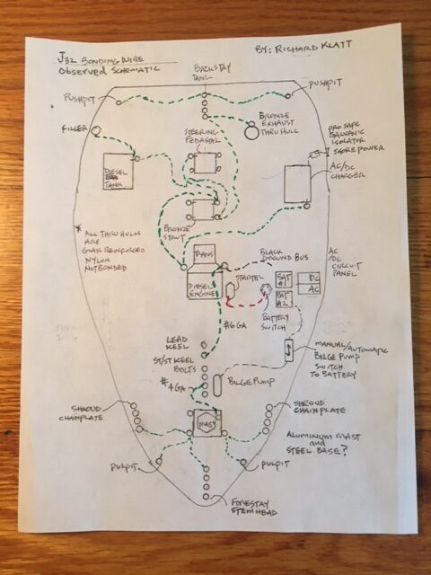
There is a bonding system that connects all the metal parts above and below the waterline. All the thru hulls are nylon except for the exhaust outlet. I will attach a diagram of that bonding system as I observed it which agrees with the diagram in the owner’s manual.
The 2- to 8-year-old AGM batteries consistently maintain a 12.7-volt charge from week to week between day sails. I give them a 12-hour charge every month with the on board charger plugged in to shore power to boost the normal alternator charging while motoring.
The Sun Fast 37 in the slip next to me has the same shaft and strut configuration even the same prop and has no sacrificial zinc loss for the whole season. He always plugs in to shore power.
It is disconcerting that I haven’t been able to find a professional to diagnose the problem, like it is black magic. I hope you will be able to help us to find a solution.
Respectfully,
Richard and Eva Klatt
Richard:
The bonding system schematic is revealing in that in several cases, including the strut, backstay, engine, mast step and pedestal, the bonded components are used as conductors, i.e., bonding wires’ ring terminals are connected to different, rather than the same, fasteners thereby making each of these components part of the circuit; this is referred to as “daisy chaining” and it is discouraged. In addition to potentially being non-compliant, this approach can lead to higher than ideal resistance in the bonding system, and under-protection for submerged components that are at or downstream electrically from the daisy chained item(s). The goal for resistance between bonded components and sacrificial anodes is a mere 1 ohm, a very high standard indeed. Therefore, I recommend that be corrected as soon as possible.
Anecdotal anode consumption rates can be misleading, they are a function of the area of, and alloy being protected, salinity, water temperature and movement. The anode on the shaft is protecting the shaft and the prop, and so in theory it and the anode on the prop should deplete at the same rate, assuming the connection between the shaft and prop is of low resistance, and the two anodes are of the same composition. This can be tested with an ohm meter while the vessel is hauled. However, if these are the vessel’s only anodes, that’s another matter, more on that below.
Cutless bearings are prone to corrosion because the bearing’s shell is, in most cases made from brass, which otherwise should never be used in below the waterline applications. That’s intentional in this case, as it is less noble than the strut, so it will corrode prior to the strut via a corrosion phenomenon known as dezincification, which is described here. Incidentally, the opening photo in that article is a dezincified Cutless bearing, this is common, it is not harmful per se other than to the bearing, which is of course replaceable. It is avoided with cathodic protection, i.e., making certain the strut is protected by a sacrificial anode, either directly attached to the strut or via the bonding system. More on that here.
Without seeing detailed photos of the original corroded strut, it’s impossible for me to even speculate on the cause, it could have been the result of the incorrect alloy having been used, or a stray current issue. If the strut had a pinkish hue, that would be indicative of dezincification, which would confirm the incorrect alloy was used. If it was heavily pitted, with areas of rough, bright metal, that’s indicative of stray current corrosion. Based on the photo you provided of the current strut, I see no evidence of corrosion.
Once the bonding wire “daisy-chaining” is corrected, and while the vessel remains hauled, the continuity of the bonding system should be tested. The standard, as noted earlier, is no more than one ohm of resistance should exist between any bonded component and an anode. As far as I can tell, from your description and the schematic, the only anodes you have are for the shaft and prop. If so, they are not protecting all other underwater metals. The continuity path between and through a shaft, transmission and engine, to the bonding system, is usually tenuous because the latter two are oil-filled; it’s not a connection that can be relied upon, so whether or not your shaft anode is indeed protecting other underwater bonded metals is unknown, but unlikely. However, two-month consumption of a shaft anode, if it was protecting the other bonded metals, would not be unusual, and it is not in any event indicative of stray current corrosion, which is much more vociferous and rapid. More on that here.
Finally, once the vessel is re-launched, a reference electrode test should be performed to determine the protection level of the underwater metals, including the shaft/prop and the remainder of the bonded components. You can read more about that process here. Without this test, any corrosion analysis is purely speculation. I suspect, based on the information provided, the underwater metals are under-protected and that a hull anode should be added, but again, the reference electrode test will confirm or refute this supposition.
Good morning Steve,
I am hoping you can assist me. We are cleaning out a relative’s house and there is a un-deployed, canister-style 8- person life raft. We want to get rid of it but have not been able to find out how to dispose of this, or who might be able to take the life raft. It has never been opened and is from 2015.
I have attempted to contact the company it was purchased from and a few other companies here in Canada, but have not had any response. I know it cannot be safely opened by us, because of the release and how the canister will be thrown apart, and definitely do not want to put it in a dumpster.
Could you advise how we can get rid of this safely?
Thank you so much for any information you can provide.
Jan Caroleo
Jan:
That’s not considered a very old raft, so it seems a shame that it can’t be given to someone. I would imagine you could give it to a liferaft repacking facility.
Barring that, there are YouTube videos of rafts being tested manually by pulling the painter to its end and deploying the gas canister. It can be moderately violent, but if you are standing at a safe distance, 20 feet or so, it is not dangerous. Here’s one example.
Once deployed, you could simply throw it away.

