
From the Masthead

My kingdom for a set-screw…
The headline is an eye-catcher for any gearhead, “The incorrect installation of a single set screw led to the loss of propulsion control on the Canadian-flagged, 736-foot-long Atlantic Huron, causing the ship to strike a pier at 6.8 knots, the National Transportation Safety Board said Tuesday.”
It goes on to say, “…contact between the self-unloading bulk carrier and a pier associated with the Soo Locks, in Sault Sainte Marie, Michigan, resulting in $2.2 million in damage. There were no injuries.”

Here’s where it gets interesting, “NTSB investigators traced the problem back to a small set screw that was installed in a piece of the controllable pitch propeller machinery that controlled pitch. Vessel maintenance records show the set screw was last removed and reinstalled during a shipyard period more than four years before the accident.”
Four years, and who knows how many tens of thousands of miles, before the accident.
“When the set screw was examined post-accident, technicians found no evidence that any manufacturer-required thread-locking fluid had been applied.”
Essentially, a few drops of LocTite.
“As a result, the set screw was able to back out, beginning a sequence of mechanical failures that resulted in the ship moving ahead when it was supposed to be doing the opposite, while still indicating an astern pitch on the ship’s bridge.”
$2.2 million in damage, and that does not include the loss of revenue from the ship being removed from service for repairs, all for want of a tight set screw.
I’m often accused by brokers, boat yards and builders of obsessing over small details, often followed by the words, “Steve, what are the chances of that failing?!”. But their characterization of me is inaccurate, I obsess over all details.
If you are a vessel owner or operator, you should be attentive to the systems aboard your vessel, including details large and small, you must carry out routine inspections, both formal and informal, for more on the latter see The Boat Genie.
If you are in the marine trades – managing or working in a boat yard, a field technician, an after market installer, or a boat builder – remember, every job, regardless of size, consists of a series of details, sometimes a few, when installing a hose clamp for instance, or a few thousand, if you are building an entire boat. In the end, every one of those details adds up to one of two things, failure or success; which one is entirely up to you.
This month’s Marine Systems Excellence eMagazine article covers the subject of fuel system vacuum gauges. I hope you find it both useful and interesting.
The Invaluable Vacuum Gauge
Where fuel systems are concerned, vacuum gauges are among the simplest, and most valuable, of troubleshooting tools.
I regularly receive emails and phone calls from clients, readers and colleagues around the world seeking assistance with onboard systems problems, troubleshooting or repairs. Interestingly, and perhaps not surprisingly, an inordinate number of these communiqués involve fuel systems.
In one memorable example, a client emailed me requesting assistance with an engine and generator that would routinely shut down when either were heavily loaded, but otherwise ran well. There were no overt signs of trouble, no leaks, no overheating and no apparent electrical problems. Hold that thought.
Most boat owners aren’t trained mechanics and in spite of the fact that some vessels are well-equipped, with a full set of hand tools and spare parts, few carry a true complement of engine or systems diagnostic instruments. As a result, as I work though a troubleshooting tree with an owner or crew, I simply have to make do with asking a series of questions that lead me, and subsequently them, in the right direction using the tools and components at hand.
There are, however, a few fuel system troubleshooting tools and techniques that you can exploit, regardless of your skill level. Undoubtedly, chief among these is the humble fuel filter vacuum gauge. The vacuum gauge is perhaps the single most valuable tool where fuel system analysis is concerned, and its value as a troubleshooting aid is disproportionate when compared to its meager cost. A basic vacuum gauge typically costs less than some OEM oil filters.
A vacuum gauge should be used to drive fuel filter changes; a rising vacuum reading is indicative of a filter that is progressively retaining more contaminants. My preference is to replace fuel filters annually, or if the vacuum reading climbs into the yellow, whichever comes first. Additionally, it can be used as a troubleshooting tool. If an engine begins to run erratically or lose power, if the vacuum reading is normal, fuel system components up stream, i.e. primary filter and plumbing back to the tank, can be ruled out as potential culprits, potentially saving considerable troubleshooting time and effort. More on vacuum readings below.
In order to effectively utilize a vacuum gauge for fuel system analysis or troubleshooting it must, A – be properly installed, B – the user must understand how it works and how to read and set it, and C – it must be monitored. Typically, vacuum gauges are installed at or near the primary fuel filter. All Racor tandem series filter assemblies include a vacuum, or in older models a compound pressure/vacuum, gauge. The pressure portion of the compound gauge is typically not relevant, unless the filter is installed well below tall fuel tanks that feed from the bottom, in which case it’s possible that the fuel supplying the filters will be under pressure and the gauge may indicate this.
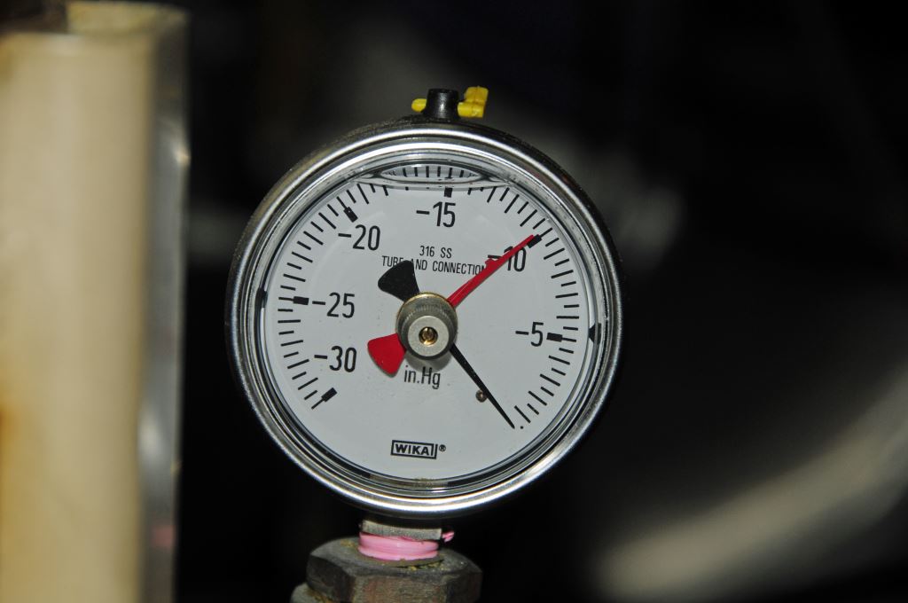
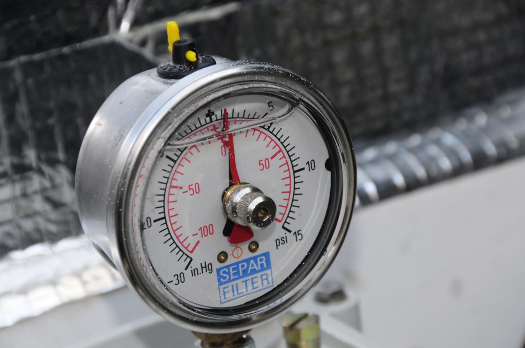
Many older vacuum gauges utilize a compound scale, one that shows both pressure and vacuum. The former is of little value as primary fuel filters are typically used in vacuum applications. This gauge is registering an extremely high vacuum, an indication of a clogged filter or blocked fuel line.
While this is not harmful in and of itself, and while Racor turbine series filters are capable of working under as much as 15 psi pressure, vacuum or suction applications are recommended by the manufacturer; and that’s how the vast majority are installed.
If the filter is placed under pressure, whether by virtue of its installation location and fuel tank plumbing arrangement or, if an electric priming or auxiliary fuel pump is placed between the filter and the tank, and it’s operated continuously rather than simply for priming, then this may lead to an insidious problem whereby the vacuum gauge gives no indication of filter clogging because the vacuum is being offset by the fuel pressure, creating an equilibrium of sorts. This scenario may exist until enough contaminants accumulate within the filter element, at which time the vacuum will increase precipitously, leading to rapid fuel starvation. Avoiding this scenario is easy; ensure that you don’t continuously pressurize the primary filter with an electric pump while underway. One exception to this rule involves small lift pump located far from fuel supplies, a common scenario with genset installations on larger vessels; those may actually need the continuous assistance from an electric booster pump.
For single Racor or other primary filter installations, the vacuum gauge is best placed immediately adjacent to the filter body on the outlet side of the filter. Remember, its primary mission is to measure vacuum between the lift pump on the engine and the filter element (which is driven by either filter condition or restrictions in the fuel system all the way back to the tank’s pickup tube). The reason for this is their main function is to monitor the condition of the primary fuel filter element, as the element becomes impacted with contaminants, the level of effort required for the engine’s fuel lift pump to pull fuel through the filter increases, as does the vacuum imparted on the fuel system between the lift pump and the primary filter. Excessive vacuum can not only lead to engine running issues, it can induce vacuum leaks, where air is drawn into the fuel system plumbing, and air is the archenemy of diesel fuel injection systems.
Identifying the presence of and locating vacuum leaks can be challenging. One means of determining if you have a vacuum leak is to perform a ‘decay test’. This test essentially tests the vacuum-tight integrity of the fuel system between the lift pump and the isolation valve at the tank (all fuel tanks should have isolation valves at supply plumbing). With the engine running, slowly close the supply valve at the tank, while monitoring the filter’s vacuum gauge. The needle should rise slowly; when it reaches 10 inches of mercury, shut down the engine. The gauge should hold that vacuum after the engine stops, if it falls you have a vacuum leak somewhere between the lift pump and the tank valve. For large fuel systems, if you install another valve on the output side of the filter, after the vacuum gauge, that will allow you to isolate the section of fuel system, which includes the filters, between that valve and the isolation valve on the tank, thereby narrowing down the location of the vacuum leak.
With a primary fuel filter vacuum gauge, this impacted filter scenario, which led to an unplanned engine shut down, is very unlikely.
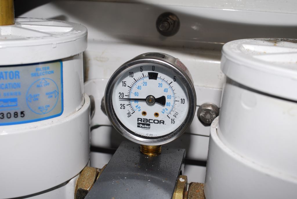
Installing the vacuum gauge in place of the filter’s T access handle, as is commonly done, works and it’s designed by Racor and after-market manufacturers to be installed in that manner, however, I’ve always considered this type of installation to be less than ideal for three reasons. First, in some cases the T handle must be eliminated to accommodate the gauge, which makes the filter more difficult to service (a wrench is now needed where before no tools were required). Two, the gauge is more susceptible to damage each time the filter is serviced. Three, when located atop the filter body, the delicate gauge is subject to damage from people, gear and tools as they pass by. I once saw a mechanic knock a gauge clean off as he carried a battery through an engine compartment.
While any vacuum gauge is better than no vacuum gauge, those that take the place of the filter’s T handle have drawbacks, including susceptibility to damage, and the need for tools in some models to service the filter. The red line at the 5:00 o’clock position is adjustable, it is adhered to the gauge lens, and can be set as a reminder of your own maximum vacuum threshold.
Ideally, the gauge should be hard plumbed to the filter’s outlet fittings (such a fitting is available off the shelf for 900 and 1000 series filters, however, it must be made-up for the 500 series filters which is easily accomplished), where it can be positioned for easy reading and remains out of harm’s way. Alternatively, the gauge can be remotely plumbed for more convenient reading, inside or outside the engine room, at the helm or adjacent to an electrical panel in order to provide casual monitoring. For longer vacuum gauge plumbing runs, those over approximately 12 feet, hard metallic (and thus flame-resistant), tubing should be used rather than hose. Hose runs beyond this length, even USCG flame-resistant A1 fuel hose, can lead to inaccurate gauge readings. Plastic tubing should never be used for this application; if hose is used for shorter runs, it must be be USCG Type A1. Plumbing for remote gauges should be connected to the fuel system at the primary filter’s outlet fitting, or at the proprietary gauge location on a tandem filter.
The outlet plumbing is the most desirable location for a vacuum gauge on a single primary filter. Here it can remain permanently installed, and it is protected from damage.
Most, but not all, vacuum gauges are equipped with an equalization valve or rubber plug located at the top of the gauge body. This valve should either be left open, to ensure the gauge’s Bourdon tube is exposed to atmospheric pressure, which will yield accurate pressure readings, or it should be cycled before reading the gauge.
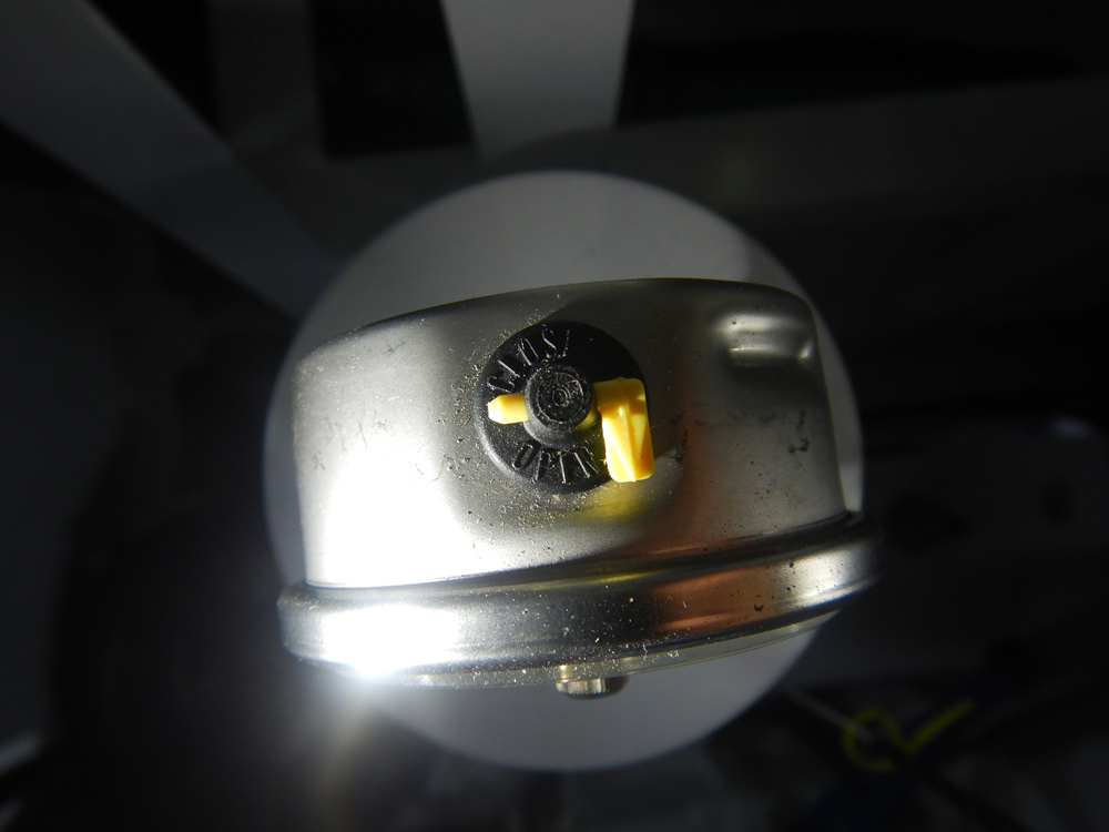
Some (they are typically the liquid-filled variety), but by no means all vacuum gauges include equalization valves, which allow the pressure inside the gauge to match that of atmospheric pressure, thereby improving accuracy. The valve’s rubber base is labeled, albeit with very small writing, OPEN and CLOSED, with a corresponding arrow on the valve handle. Under normal conditions, and if the valve is installed vertically, the valve can be left in the open position.
If this is the rubber plug version, it will need to be partially dislodged with a fingernail or small screwdriver, which is makes it prone to popping out of its recess, or worse falling into the gauge, where it’s almost impossible to retrieve. Vacuum gauges are optionally available in a liquid-filled variety; which dampens needle movement, which prolongs its life and improves ease of reading, as well as reducing vibration-related damage to gauge components. My preference is for both equalization valve-equipped, and liquid-filled gauges.
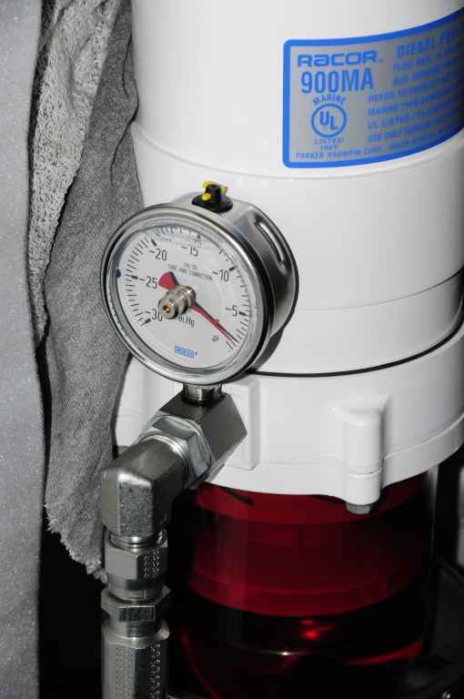
Higher quality vacuum gauges are often equipped with an equalizing plug or valve (the yellow handle shown here), which is used to ensure the Bourdon tube is exposed to current atmospheric pressure, which is required for greatest accuracy. When cycled from closed to open, a shift in the vacuum reading can often be observed.
Gauges that are equipped with drag or recording needles, or re-settable pointers, these are usually red, while the primary needle is black, are especially useful – mandatory in my opinion – in that they record the highest vacuum experienced by the system, which can be viewed at any time, even after the engine has been shut down. It’s important to remember, the fuel system vacuum is typically greatest when the engine is operating at cruising or full rpm, checking the vacuum while the engine is idling, or off, will not offer the user an accurate indication of the filter element’s condition. With a drag needle, the operator no longer needs to walk, climb or crawl into the engine room while the vessel is at cruising speed (not that there’s anything wrong with that, regular engine or engine room checks should be standard operating procedure for all vessels, for more on that subject see this article) in order to ascertain fuel vacuum readings.
One caveat where drag needles are concerned, they can very easily be turned 360 degrees so their stop is on the wrong side of the primary, black needle. In that case, they will never move, thereby providing a false zero reading. Look carefully and make certain the needle is positioned so it will be dragged upwards with the primary needle.
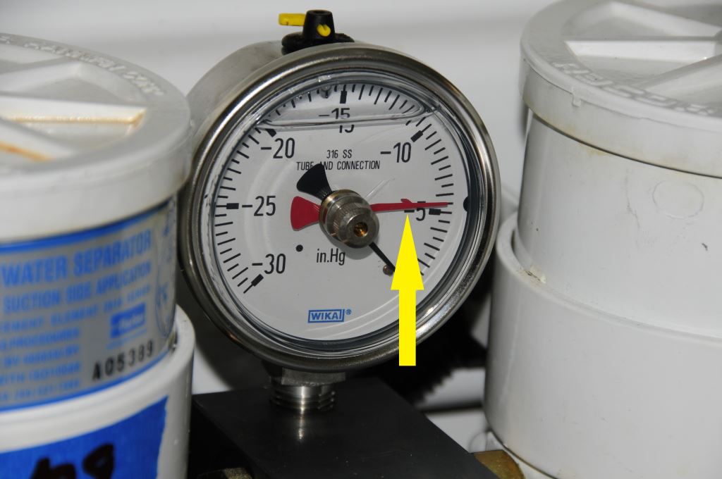
Drag needles will only work properly if the needle is positioned on the correct side of the primary needle, where they can act on the drag needle’s tab, highlighted here by the arrow.
Unless you look carefully, you might miss the fact that this gauge’s red drag needle is on the wrong side of the black primary needle, which means the former will not move.
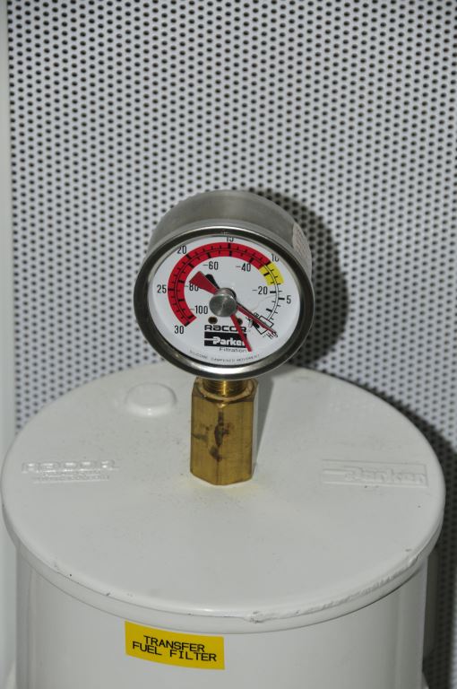
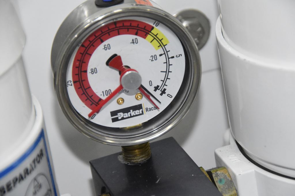
Most fuel filter vacuum gauges include a scale that runs from 0 to 30 inches of mercury, the latter being a perfect vacuum, something no fuel system is capable of imparting. While that range is traditional, it’s less than useful as the average diesel engine potentially enters extremis when the vacuum exceeds anything over 5-7 inches of mercury. Therefore, the bulk of the scale is useless. Some vacuum gauges, on the other hand, use an expanded scale, which ranges from 0 to 15 inches of mercury, making them more practical and precise for this application; Dent Marine LLC offers just such a gauge.
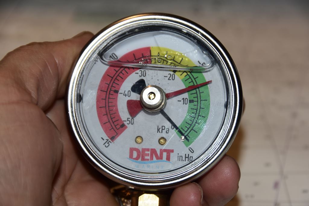
A liquid-filled vacuum gauge with drag needle. This gauge, From Dent Marine, uses a unique expanded scale, making it more useful and precise for the commonly encountered lower vacuum readings encountered on diesel engine applications.
Using the vacuum gauge for fuel system analysis and troubleshooting may seem intuitive and for the most part it is. If the vacuum increases beyond a given threshold, the filter needs to be changed. A baseline must be established with clean filter elements, however, in order for the vacuum gauge’s readings to be meaningful. If, with clean elements the vacuum is one or two inches of mercury, this essentially becomes your “zero set point” and it should be recorded on a tag or label adjacent to the gauge. Meaning, obviously, anything over this is a result of clogging or a fault. If the zero-set point is high, say above 4 inches of mercury (most vacuum gauges are calibrated in inches of mercury, anything over about 7 is considered high, although virtually every engine manufacturer sets their own limits, check yours) the system has other resistance to flow problems that must first be addressed. If no notation was made of the vacuum with clean elements, with the engine under heavy load, then calling on the vacuum gauge to assist in troubleshooting an operating problem later will be more challenging. If the system always ran at 7 inches of mercury (which is too high) then this reading may lead to chasing faults that don’t exist or they may exist elsewhere in the system. High vacuum, by the way, can lead to reduced fuel lift pump life as well as cavitation erosion within, and failure of, the injection pump, an especially costly component.
Vacuum gauges can be tested by restricting the fuel supply to an engine while idling, in neutral, dockside. This can be achieved by slowly rotating the fuel supply valve at the tank or manifold toward the closed position, it should not be necessary to close it fully, while watching the vacuum gauge, as the supply is restricted, the gauge’s needle should begin to climb. While this is not a test for accuracy, if the needle doesn’t move, you know there’s a problem. Be sure to restrict the supply and not the return, return fuel flow should never be shut off while an engine is running.
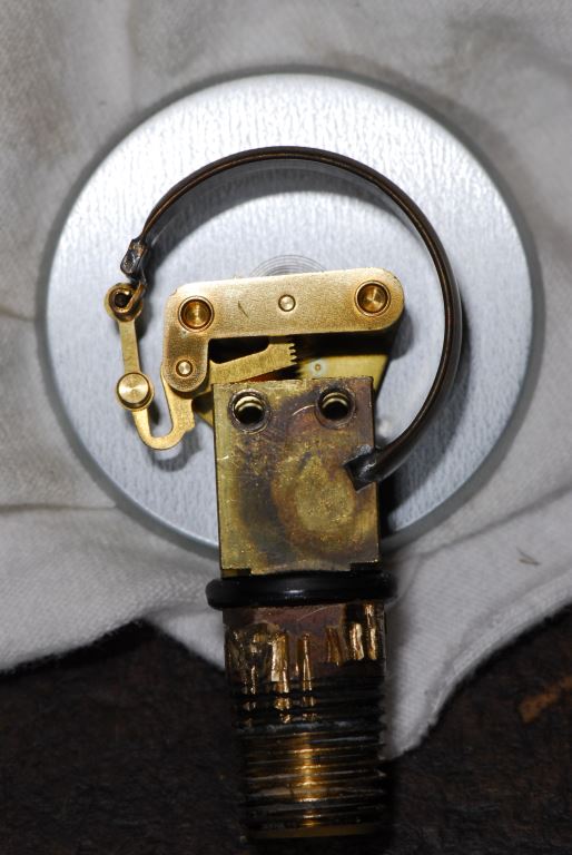
The “guts” of a vacuum gauge, the C-shaped band is the Bourdon tube, it is pressure sensitive and acts on the gauge’s needle via the gear. These components are delicate, and while liquid-filled versions are more rugged, gauges that have been dropped or jarred heavily should be replaced as their accuracy may be affected.
In the case mentioned at the beginning of this article, the engine and generator that shut down under heavy load, while I was able to assist the operator in identifying the problem using the system’s vacuum gauge, the problem itself was not as straightforward as one would have hoped. Initially, based on the high vacuum readings, in excess of 15 inches of mercury, I suspected the obvious, the fuel filter was clogged. The client reported that indeed, it was clogged and I was confident I’d helped him to solve a problem, albeit a minor one. I received a follow up message; however, a day later indicating the problem remained along with the excessively high vacuum, the clogged filter was a red herring. After conducting a few more tests, by drawing fuel from a different tank and monitoring vacuum changes, I concluded the blockage was either in the tank itself, at the fuel pickup, or worse, inside the manifold. As it turned out, the blockage, a small piece of heavy manila paper that appeared to have once been a string tag, was periodically being sucked up into the fuel pickup tube inside one of the tanks. Each time that happened, the vacuum readings rose, causing the engine and/or generator to shut down. When the engine shut down, the vacuum would dissipate and the paper would fall off of the pickup tube; an insidious yet not uncommon scenario for tank debris. The vacuum gauge carried the day by making it clear that there was a blockage of some sort between the lift pump and the tank. With that information this part of the fuel system could first be isolated (using another tank supply) and then carefully scrutinized to find the source.
The level of return on investment for a fuel system vacuum gauge is undeniable. On a day-to-day basis it will allow you to change filters when necessary, rather than based on perceived need, or worse when the engine begins to run erratically. When more challenging fuel system problems arise, the vacuum gauge serves as a built-in troubleshooting tool, one I wouldn’t be without.

