
Text and photos © 2021 Steve D’Antonio Marine Consulting, Inc.
From the Masthead

I’m writing this column, while lying alongside a dock in Portland, Oregon, having just completed an eight-day passage from Kennewick, Washington, via the Columbia River. The trek took us through a range of topography and climate, from brown, arid desert hills, where the temperature exceeded 117°F (47°C), to temperate, wet, misty and very verdant rain forest, whose “chilly” 60°F (16°C) temperature proved a welcome respite to the crew. It represents my first “desert cruise”. We passed through four locks, each associated with a dam, with river conditions ranging from glassy calm, to 40 kt winds and three-foot waves.

While not without their controversy, the locks and dams represent incredible engineering marvels, to see, and use them up close, was a treat for this gearhead. The total drop from Kennewick to Portland, via the McNary, John Day, The Dalles and Bonneville Dams/Locks, is an impressive 340’ (102m).

Wildlife is abundant, including deer, turkey, a variety of fish including salmon and sturgeon (a “prehistoric” fish that has no scales and looks the part, they are North America’s largest and longest-lived freshwater fish, reaching a maximum size of 19 feet (6m) and1,800 pounds (800 kg)) eels, bats, pelicans, swallows and a range of other birds.

Of course, if you are an American history enthusiast, and I am, you’ll know that the Columbia River represents the final leg of the epic Lewis and Clarke expedition, an event in which the entire region is steeped. A day driving trek to Mt. Hood’s historic Timberline Lodge, a 1930’s WPA project, added yet another dimension to this otherwise waterborne passage.

Entering Portland means a return to civilization, my least favorite part of any passage, however, it also means returning to my home and family. Cruising in this manner, by small vessel, close to the surface, and anchoring in remote bays and coves, brings one closer to the land and its inhabitants, those of the two and four legged, as well as winged and scaled, variety. I can think of no better way to travel.

This month marks the return of the Marine Systems Excellence eMagazine, from my crunched schedule-induced hiatus. The feature covers the subject of engine room checks, I hope you find it both useful and interesting.
Engine Room Inspection
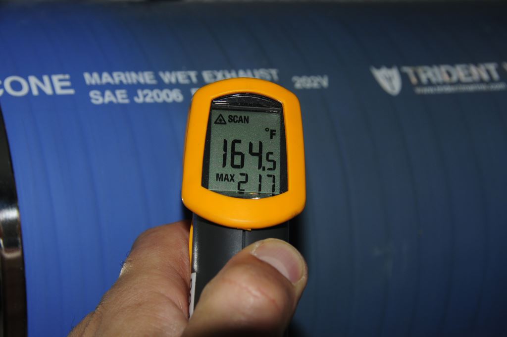
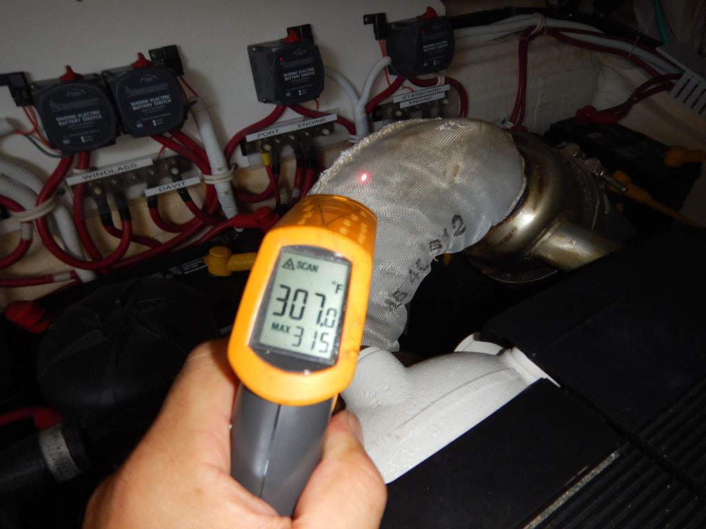
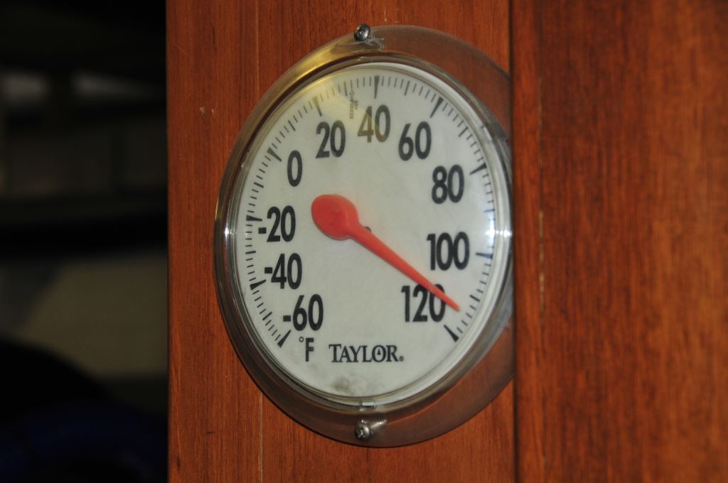
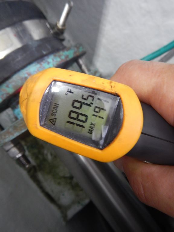
No part of an exhaust system that can be touched should exceed 200°F (93°C). The one shown here is too hot.
When two clients ask me, in the same week, if I’ve written an article on a particular subject, I pay attention. In both cases I’d recently completed reviews of their vessels, one in-person, for a 17-year owner, and the other remotely, for a foreign buyer. During the ensuing discussions a range of subjects were covered, from correcting defects, to improving the safety, reliability or operation of specific systems or components, which eventually led to, “what do I look for when checking the engine room while underway?” question.
Engine Room Round Robin
There are two kinds of engine room inspections, one is static, and performed while dockside with the engines and genset stopped, while the other is underway, with engines and other gear running. In this article I’ll cover the underway inspection.
Before venturing into the engine room, make certain you are properly prepared, this includes eye (I wear reader safety glasses whenever I work, and especially around moving machinery, hot coolant, oil and hydraulic fluid etc.) and ear protection, while ensuring you are wearing no jewelry that can catch on machinery or conduct electricity, which includes metallic rings and watch bands, and you have no loose clothes, drawstrings or exposed ponytails. I make it a point to wear shoes in machinery spaces, even if the boat is shoeless, as they offer better footing, while protecting my feet and especially toes.
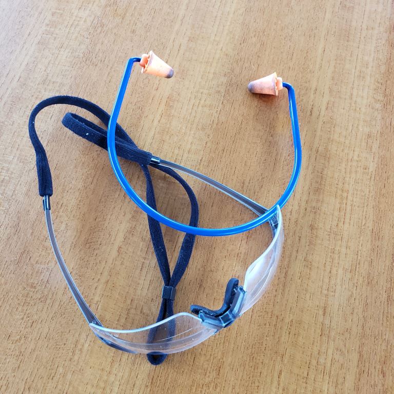
Both eye and ear protection are mandatory for working in engine rooms.
A few years ago, while performing an underway inspection in stocking feet, I slipped on a slick gelcoated deck, and my foot made contact with the rotating shaft coupling, which was equipped with a safety wire-secured set screw. The sharp edge of the wire caught my sock, yanking it cleanly off my foot. I was unharmed but it left me startled, with a lesson learned about being barefoot in the engine room. On one occasion, while conducting an engine room inspection, just as I was about to close the door behind me, a coolant hose separated from a pipe adapter (it was in fact a threaded pipe nipple, which is inappropriate for terminating hose), which immediately released the entire contents of the engine’s cooling system and keel cooler, gallons of 195°F (90°C) coolant and vapor. After that sobering episode, I vowed to always wear safety glasses in engine rooms.
If that lesson isn’t clear enough, I’ll reiterate; you must remain alert while performing these underway inspections, especially while you are near moving machinery such as belts, pulleys and propeller shafts, and hot parts, including the dry exhaust, turbo-chargers and turbocharger charge air plumbing. A misplaced finger, hand or forearm could end in a nasty burn or an amputation, I’ve experienced the former first-hand, and witnessed the latter, when momentarily blinded mechanic (he had just come from bright sunlight) lost his thumb after inadvertently placing it between a turning belt and pulley.
Many older engines do not utilize belt guards; exercise extreme caution around these, especially in a seaway where it’s easy to be thrown off balance.
The tools that are needed for an underway engine room inspection are simple and inexpensive, an infrared (IR) pyrometer and a small flashlight. While the order of the items you inspect isn’t especially important, it makes sense to do so in a geographically logical manner, i.e., if you make a circuit around the engine room, inspect each item as you come to it, avoiding backtracking, and then make that your route every time thereafter. Once that route is established, prepare a checklist that you can follow, at least initially, as a prompt, to prevent you from missing anything. For more on infrared pyrometer use, see this article.
What to Check
Coolant: I’m a big fan of coolant recovery bottles, they serve as excellent visual status indicators for an engine’s cooling system. If your engine doesn’t have one, in most cases it can be added. Using tape, mark the level in yours when cold, then again after the engine has reached its full operating temperature and has been running for at least an hour. These two indicators will provide a quick visual reference, the coolant should return to these two marks when cold and hot, if it doesn’t, you’ll know right away something is wrong. For more on coolant recovery bottles see this article.
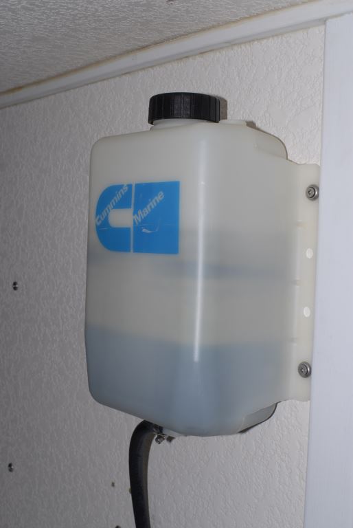
Coolant recovery bottles are windows to a vessel’s cooling system, ideally their hot and cold level should be marked with tape.
If you know where your engine’s coolant temperature sender is, using your IR gun check that, as this will confirm your gauge reading is accurate. It should be within about 5°F (3°C) of the gauge on the instrument panel.
Alternator(s): If your vessel has the ability to monitor alternator output specifically, using an ammeter for instance, you should make that part of every engine room check, even if the gauge is somewhere other than the engine room. It’s important to note, if you are underway, with a genset running, which in turn is powering a battery charger, it’s very possible that alternator output will drop, potentially to zero. This is entirely normal, as the alternator’s regulator “sees” the higher voltage supplied by the battery charger, which signals it to reduce or eliminate its own output. Beware, however, this scenario can mask a non-functioning alternator, and as such it’s important to periodically confirm alternator output with no other charge sources present. If your vessel is not equipped with an alternator ammeter, then you should consider confirming alternator output using a digital multimeter that is equipped with an amp-clamp. While many engine instrument panels will measure voltage, or net amperage, it is not a completely reliable means of confirming proper alternator function, as that volt meter will register voltage and current from any source, a battery charger, inverter charger, solar panels, or even another engine’s alternator if the two are paralleled, which is connected to the same battery as the engine/alternator. More on multimeter selection and use in this article.
While on the subject of alternators, their temperature should be measured using your IR gun, or a permanently-installed probe associated with a vessel monitoring system, or the wired remote probe from a digital thermometer. The hottest portion of an alternator is usually the stator, essentially the center of the barrel-shaped portion. Squeeze the IR gun’s trigger and while doing so wave it over the entire body of the alternator, while holding it as close to the alternator as possible (again, be mindful of moving belts, pullies and the fan). This scan feature will yield the highest temperature.
Alternator temperature should be checked at the hottest section, typically the stator, preferably while it is heavily loaded.
While it varies from manufacturer to manufacturer, typically, large frame, high output alternators designed for continuous duty can endure temperatures as high as 300°F (149°C) for short periods, and up to 240°F (116°C) for longer stints.
Belts: If visible, carefully eyeball your belts, idlers, sheaves and tensioners, as well as the area directly below the front of the engine, for generation of excessive dust. The only way to know if your belts are generating dust is to keep the front of the engine clean. If it’s caked with years’ worth of accumulated belt detritus, and oil, you’ll have no way of knowing if this the legacy of a since corrected problem, or if it’s newly generated. For more on belts, see this article The belt analysis is best conducted at rest.
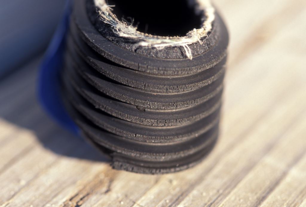
Belts have a finite life; this one is well past its replacement interval. However, the white filament is also a telltale sign of a worn tensioner pulley.
Exhaust: The engines dry exhaust system, the portion between the engine’s exhaust manifold or turbo-charger and seawater injection point (or the whole accessible run if it’s a dry exhaust vessel), should be monitored using your IR pyrometer. Beware, while IR pyrometers are generally very accurate, they can be fooled by highly reflective surfaces like polished stainless steel, chrome and foil-faced insulation; the latter is commonly used on dry exhaust systems. In that case, areas where you intend to measure can be painted with flat black paint, or black tape can be applied, a small square is all that’s necessary. The ABYC Standards mandate that if your measurements exceed 200°F (93°C), on any portion of the exhaust system you can touch, they are too hot; they must either be insulated more effectively, or guarded to prevent contact.
Be sure to check the turbo-charger; “dry”, non-liquid cooled turbos must be insulated, as well as the flange between turbo and exhaust riser, in many cases it is entirely exposed. I’ve measured some of these at over 500°F (260°C).
The temperature of wet exhaust systems should be checked through the full range of operating rpm, they will often run hotter at lower speed, when less water is pumped into the system.
As a side note, even if adequately insulated, an underperforming engine room ventilation system can lead to overly hot dry exhaust surface temperatures. The reason for this phenomenon; if there is insufficient air turnover, then heat cannot be carried away from these surfaces rapidly enough to maintain the required sub-200°F (93°C) temperature. For more on engine room ventilation see this article.
From here move on to the wet portion of the exhaust system. Measure the hose immediately after the mixing elbow, especially on the top or 12:00 o’clock position, as that’s likely to be hottest. Counterintuitively, the highest temperature may be reached at lower speeds, idling even, when less water is being injected into the exhaust system. Again, no portion of the wet exhaust system should exceed 200°F (93°C); typically, it’s closer to 130°F (54°C). One of the more popular wet exhaust temperature alarms, an indispensable component on any inboard-powered vessel, triggers at 165°F (74°C). For more on those see this article.
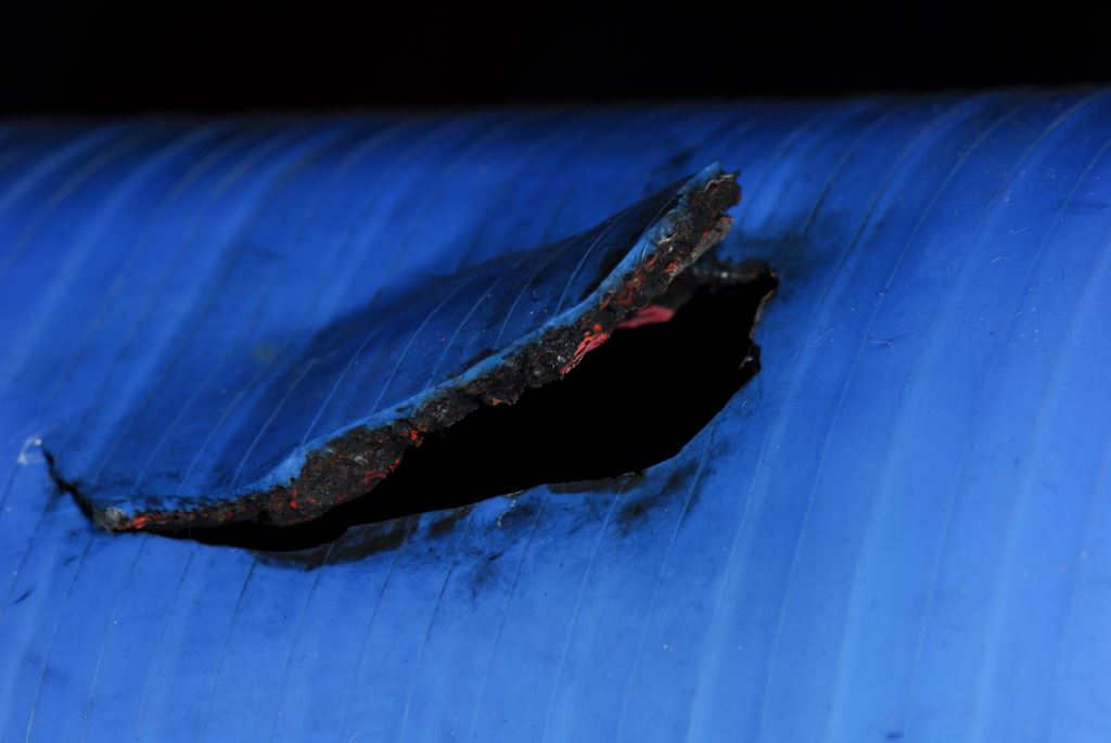

Chronic wet exhaust system overheating can lead to hose failures, and even silicone hose is not immune to very high temperatures.
Engine Room and Related Temperatures: Measurement of engine room temperature is an important metric for determining the efficiency and adequacy of the space’s ventilation, be it passive or active. Measuring this in different locations will yield different results, however, most engine manufacturers specify a maximum allowable difference in temperature, a ‘delta T’, between the engine air inlet, typically measured at the air filter, and ambient, the air outside the vessel (the outside temperature must be measured in the shade). While Cummins and John Deere specify 30°F (17°C), Caterpillar’s requirements, as well as those of ISO 8861, are more stringent, they call for a maximum delta T of 22.5°F (13.5°C). If engine air inlet, and thus engine room, temperature is too high, the engine efficiency can suffer. However, a more insidious side-effect involves the accelerated deterioration of a variety of engine room components, including hoses, insulation, plastics and electrical/electronic components.
Excessive engine room temperature can be harmful to many components within the engine room, as well as diminishing engine efficiency.
While it’s hard to say just how much of an effect temperature has on this gear, one example is telling. The potting on many generators’ electronic voltage regulators hardens, and cracks, which ultimately leads to failure when exposed to extreme engine room heat. It’s the thermal canary in the coal mine, and is worthy of your attention; because the electrical end of a generator is air-cooled, hot engine rooms equate to gear, which isn’t good for its lifespan.
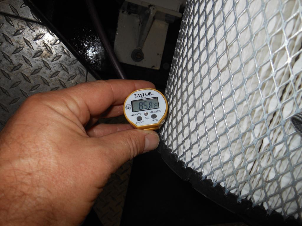
Engine air intake temperature should be measured using a wired (wireless is OK if not too bulky), digital probe type thermometer, (the one I use, made by Extech, is often used for fish tanks, it costs about $20), ideally with the probe suspended just above the surface of the filter element. While it’s tempting to use an IR thermometer, doing so will measure the temperature of the filter element itself, rather than the air passing through it; in testing I’ve done I’ve measured a disparity of as much as 7°F (4°C).
Diesel fuel is at its best when cool, at least comparatively so, it is denser, packs more BTU’s per gallon and has a higher viscosity, and therefore greater lubricity. Fuel also acts as a heat sink, carrying heat away from fuel injectors (and to the fuel tank, more on that in a moment). Keeping fuel cool is deemed so important by some engine manufacturers that they incorporate raw water fuel coolers into their fuel systems.
While you may have little control over fuel temperature, it’s a good idea to keep an eye on it, as a change could be an indication of a fuel routing, or fuel cooler problem, or another impending failure. It can be measured using an IR pyrometer, at the secondary filter (that’s the one on the engine). “Normal” fuel temperature varies with climate, seawater temperature of it is seawater cooled, engine room temperature, engine manufacturer, so it’s very difficult to give a generic range, however, keeping track of yours will allow you to identify a change.
As an aside, the heat the fuel removes from the injectors goes to the tank, and it’s close to the hull, and thus it is transferred, albeit inefficiently, to the water in which the vessel is operating. If the fuel tank is located in the engine room, some of that heat will be radiated into that space, thereby adding to the load imparted on the ventilation system.
Indirectly related to fuel temperature is fuel vacuum. Many diesel-powered vessels have vacuum gauges installed at the primary fuel filter (the one off the engine). If it’s one of the common Racor MAXX tandem series, with the selector valve, then the vacuum gauge is standard equipment. The primary reason for monitoring fuel vacuum is to determine the condition of the primary filter. As it captures more and more contaminants, the vacuum rise. Each engine manufacturer has their own threshold for allowable fuel vacuum; however, the general rule of thumb is it should not exceed 5” of mercury.
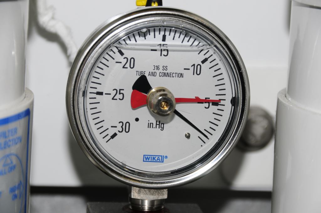
Primary fuel filter vacuum gauges are an invaluable tool in determining the condition of fuel filter elements.
Not all vacuum gauges are created equal, for more on that subject, and how to select the best one for your needs, see this article.
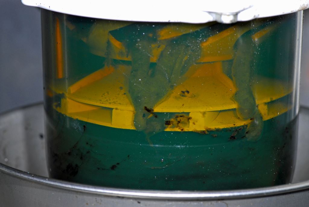
One of the beauties of clear primary fuel filters is being able to quickly determine of they are contaminated.
While you are at the primary fuel filter, and assuming it is a Racor turbine series, look closely through the bowl, and at the ports in the coalescer cone, you should see no bubbles streaming upward from any of these openings. Bubbles indicate a vacuum leak and air ingestion, which could affect engine operation, and in great enough volume could lead to an unanticipated shut down.
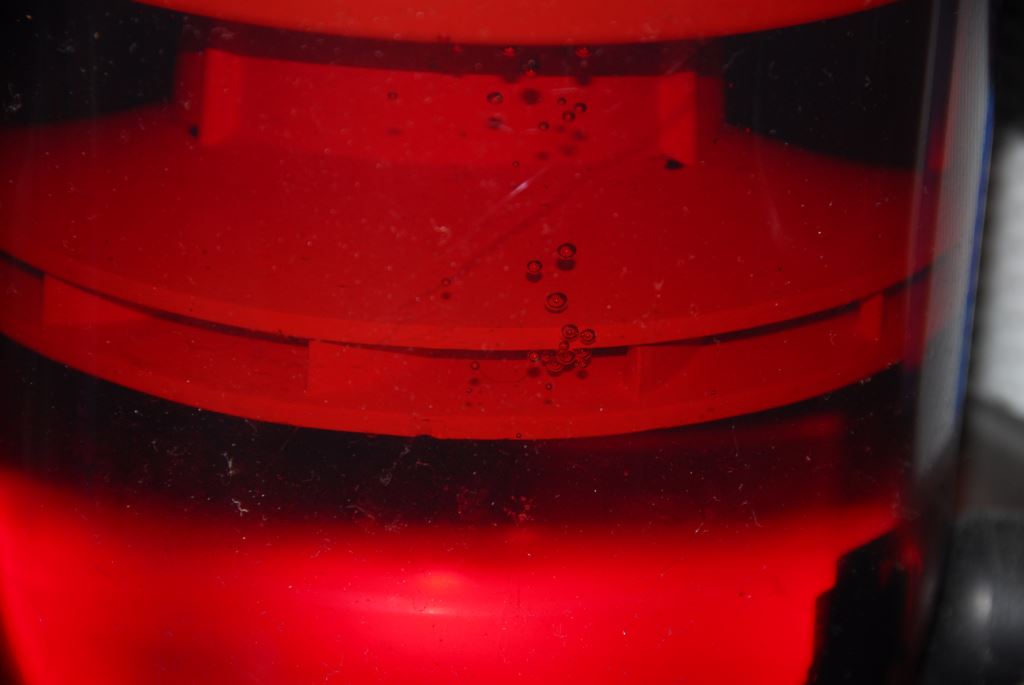
While water and asphaltene are the most common contaminants found in primary fuel filters, air bubbles are an indication of a vacuum leak in the system, one that can eventually shut down an engine. Check your filter carefully with a flashlight, any amount of air is too much.
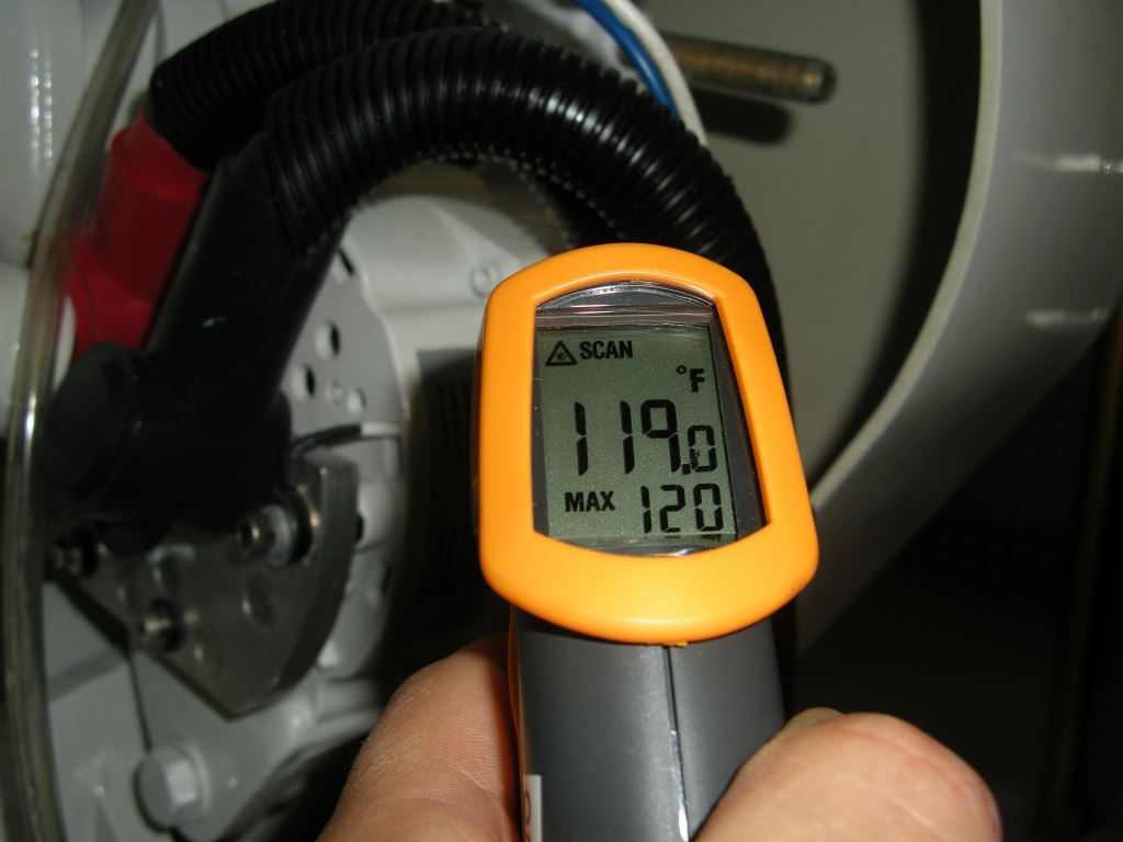
Stuffing box temperature should be regularly checked, as an overheat can lead to leakage, in some cases catastrophic if a non-metallic dripless stuffing box melts and seizes to the rotating shaft. While the rules for allowable temperature vary for different dripless stuffing box manufacturers, I have found that both conventional and dripless boxes, when properly plumbed, typically do not run over about 40°F (22°C) above seawater temperature. Because an IR pyrometer can be confused by the reflective nature of a propeller shaft, or rotor of a face seal stuffing box, be careful to keep your measurements confined to the packing or stationary seal area.
Stuffing boxes, dripless and conventional, are prone to overheating, this one is running much too hot.
If your vessel is equipped with a hydraulic system for stabilizers (and often thrusters as well), the pressure and temperature of this fluid should be monitored. It’s important to remember that if you have a hydraulic stabilizer system, the pumping action generates heat, which must be removed from the system via a heat exchanger, which is usually located near, or even within, the fluid reservoir. If that heat exchanger utilizes a dedicated seawater pump, and it fails, or the strainer becomes clogged, the hydraulic fluid will eventually overheat. If that happens, the hydraulic pump may be damaged or worse, it may seize. If the pump is “live” meaning it cannot be disconnected from its driven source, the engine timing or transmission gear, via a clutch, the seizure will almost certainly result in severe damage to the engine or transmission. The same scenario would occur if you were to lose hydraulic fluid, because of a leak or burst hose, albeit far more rapidly. If your hydraulic system begins to overheat, you should get an audible alarm before it becomes critical. Regardless, if you cannot disable the hydraulic pump(s) via a clutch, you will need to resolve the cooling problem, or stop the engine. Unbolting the hydraulic pump from its power take off (PTO) drive is yet another option. For more on this subject see this article.
You can measure the hydraulic fluid temperature by scanning the tank with your IR pyrometer and recording the highest reading, which will likely be closer to the top of the reservoir. It varies by application; however, I rarely encounter temperatures greater than about 135°F (57°C).
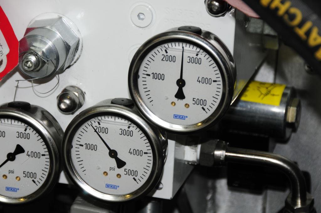
Pressure gauges offer a quick indication of the health of a vessel’s hydraulic system; check yours and make certain you know the manufacturer-specified normal range.
Hydraulic pressure is usually available on a hydraulic system manufacturer-supplied gauge, located at a manifold or the reservoir, which may be either permanently mounted, or it may require inserting a ‘test gauge tool’ into a quick connect port; clearly the latter is less convenient for routine engine room sweeps.
Running Gear: Beginning with the transmission, conduct a visual inspection, looking for leaks, signs of unusual vibration or loose hardware (hint; loose mild steel components such as fasteners and brackets, will generate a very fine brown halo around vibrating part; if you see that be sure to check carefully for something in the vicinity that’s loose). Take a temperature reading on the oil filter if present, and if not on the casing (wave your IR pyrometer around the case in the scan mode looking for the highest temp). If your engine has a wet exhaust system, then the transmission will usually be raw water cooled, which means it will run somewhere around 150°F (66°C). If, on the other hand, you have a dry exhaust, then the transmission will be jacket water cooled; it will therefore run closer to the coolant temperature.
If your vessel is equipped with a thrust bearing, an Aquadrive, Seatorque, or similar system, measure its temperature using your IR pyrometer. The primary goal here is to measure the thrust bearing housing; if it’s out of alignment its temperature will be elevated, as well as universal or CV joints, whichever of the two it may have. Temperatures for these components vary with the manufacturer and load so consult the manual for your equipment’s range, however, generally speaking Aquadrive thrust bearing housings rarely run over 170°F (77°C), while the CV joints themselves shouldn’t exceed 150°F-170°F (66°C – 77°C). Seatorque’s guideline notes a maximum temperature of 220°F (104°C), but they typically also run much cooler, somewhere around 185°F (85°C) in my experience. The U-joints will, over a longer run, operate at somewhere between 150°F-170°F (66°C-77°C). For more on thrust bearing systems see this article.
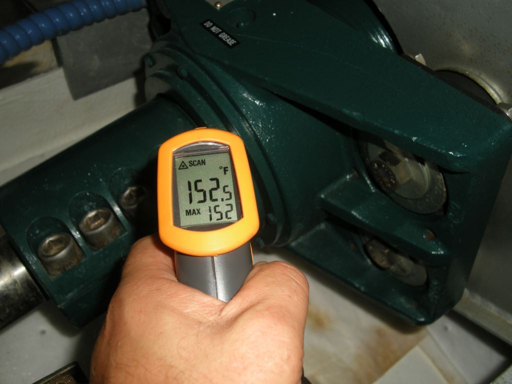
Thrust bearings like the one shown here do an excellent job at reducing onboard vibration, however, if improperly aligned they can overheat.
Motor mounts should be inspected for obvious signs of movement or loose hardware. This can and should be done during every static engine room inspection, however, you can’t look them over too often. If you can access them safely while underway (outboard mounts on twin engine applications may be tough to get to), then do so. Look as well for accumulations of rubber dust, an indication that the rubber of deteriorating, or metal to metal contact bet floating and stationary metallic parts or fasteners, which is often the result of collapsed flexible inserts. For more on motor mounts see this article.
Watch the shaft to ensure it is turning true and not wobbling from side to side; this is most easily observed by watching the stuffing box. A wobble can be caused by several defects, among these a damaged or fouled propeller, a bent shaft, a shaft that is not centered in its coupling, or a coupling that is not centered in the transmission’s output flange pilot bore (the latter two are coupling defects that necessitate coupling replacement or machining).
Finally, check the vessel’s steering system. If it’s hydraulic and powered, via a PTO, then check the fluid level, temperature and pressure (the reservoir usually has a pressure gauge). Hydraulic steering systems that operate via an engine-driven pump typically utilize seawater cooling, the water for which is usually drawn directly from the engine’s own raw water circuit. In other cases, it may rely on a dedicated pump. Either way, monitoring the temperature is important, as an increase can be an early warning of a fouled heat exchanger’ clogged intake or damaged impeller.
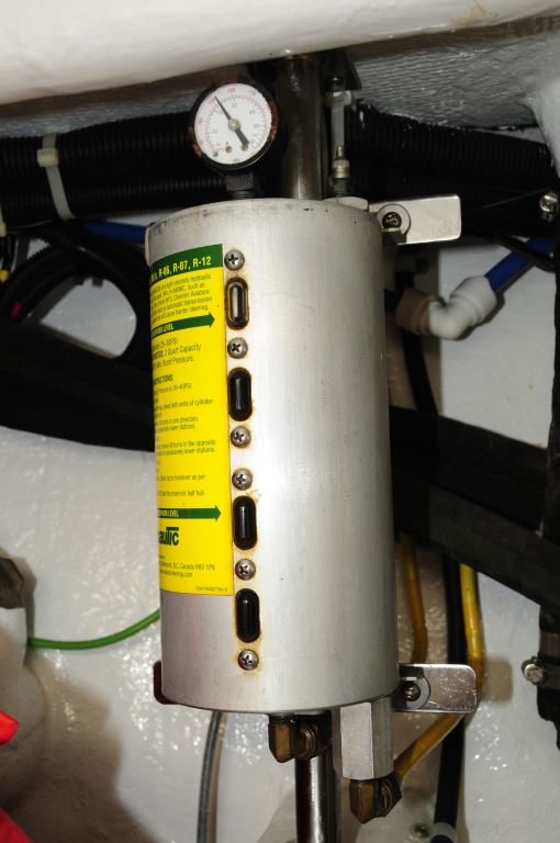
Hydraulic steering system utilize a reservoir, which is in many cases pressurized. Check both the level and pressure (this may not be in the engine room).
The temperature can be measured at the filter or reservoir. If the system is purely manual, then conduct a visual inspection of the fluid level, the rams, plumbing, valves, tie rods, and fasteners that secure the ram end(s) to the tiller arm. Loose or worn fasteners, or clevis pins (these connect two moving parts, tiller and ram end) are among my most common finds when inspecting steering systems. Check the fasteners that secure the ram to the base or shelf on which it rests. This is best done when making turns, so plan on checking this while doing some S turns at cruising speed about every 100 hours of engine time. For more on steering systems see this article.
I’m occasionally asked, “do I need to check the engine room if I have a camera in that space?” The answer is yes, you do, there’s one thing a camera still can’t do, and that’s smell. If you have a coolant or fuel leak, you are very likely to smell it as soon as you enter the space.
Without a doubt, engine room checks pay dividends, as they enable you to catch problems before they become critical, which can endanger both the vessel, and your wallet.

