
From the Masthead

Around the World in Two Weeks and Another Portable Lithium-ion battery fire
As is so often the case, I’m penning this month’s column while in flight; it’s December 22nd and I’m on my way home, hopefully in time for Christmas with my family. In the past few weeks, I’ve literally flown around the world, 1.5 times, traveling from my home in Virginia to Italy, where I spent a week reviewing a new build project. From there I flew directly to Taiwan, where I spent another week, reviewing another vessel under construction. I then flew home to Virginia for the weekend, and then returned to Italy once more, for a follow up inspection and sea trial aboard the same vessel.
While this represents a significant amount of travel, there simply is no substitute for onsite inspections of complex systems, like those found aboard today’s cruising vessels. Every issue that reveals itself to me at a yard, is one less issue that must be dealt with by a commissioning crew, and/or vessel owner.
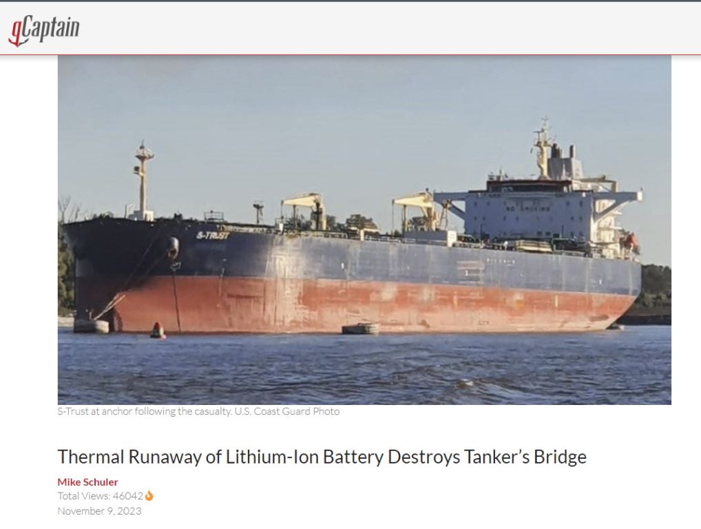
Not long ago the NTSB released a report, related to a fire that occurred on the bridge of a tanker, which was docked in Baton Rouge, Louisiana. The culprit was a handheld UHF radio, one of 20 used by the crew for shipboard communication. It, along with its brethren and chargers, lived on a “communications table” in the bridge.
I’ve written about portable lithium-ion battery fires on several occasions, I believe these present enough of a fire risk to warrant special handling, which includes ensuring charging occurs on fire-proof surfaces, and in the vicinity of a smoke detector. What’s noteworthy in this case is the fact that the flaming radio launched itself across the bridge, meteor-like, its transit caught on the bridge’s CCTV, the result of an exploding battery; a fire-proof charging surface would have done nothing to prevent this event from occurring, that would have required a fire-proof, box-like charging station. The resulting fire destroyed the bridge, causing $3m in damage, however, thankfully there were no injuries.
You can read the recently released news release and investigation report here. The bottom line is, onboard (and at home for that matter) portable lithium-ion battery charging requires caution. If a battery is damaged, becomes hot, or is failing to accept a charge normally, it should be properly disposed of, and only batteries and chargers that are UL, or equivalent, certified (the radio and charger that caused this fire was so certified), should be used. The report also recommends against unsupervised charging, however, while that is desirable, I suspect that guidance is unlikely to be followed in the vast majority of afloat and ashore cases. To reiterate, I still recommend all chargers of this sort be placed on fire-proof, ceramic or metallic, surfaces, and again with nearby smoke detection.
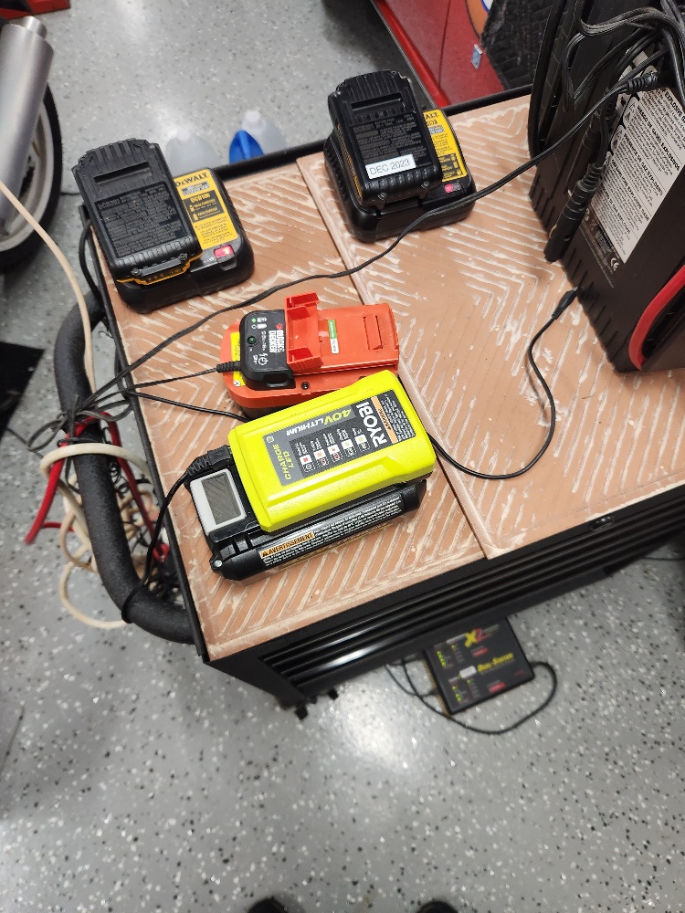
A ceramic top lithium ion battery charging station.
Surprisingly, this vessel was not equipped with smoke detection on the bridge, nor was it required to have such detection, from the report…
“Per DNV, the classification society for the vessel, the S-Trust smoke detection and alarm system complied with Method IC from the International Convention for the Safety of Life at Sea (SOLAS) 1974 (IMO/MSC.1/Circular 1456 Annex 1) for fire protection. This only required fixed fire/smoke detection in all corridors, stairways, and escape routes within the accommodation spaces. According to SOLAS, the bridge of a vessel is defined as a control station and is not required to have fire and/or smoke detectors.”
Compliance with both ABYC and NFPA standards requires the inclusion of a means of fire detection for vessels with enclosed cabins. While this may sound like common sense, I inspected a large cruising vessel only weeks ago that was devoid of any means of fire detection. For more on this subject, including type and placement guidance, see this article.
This month’s Marine Systems Excellence eMagazine feature covers the subject of de-watering flooded engines. I hope you find it both interesting and useful.
Saving a Drowned Engine
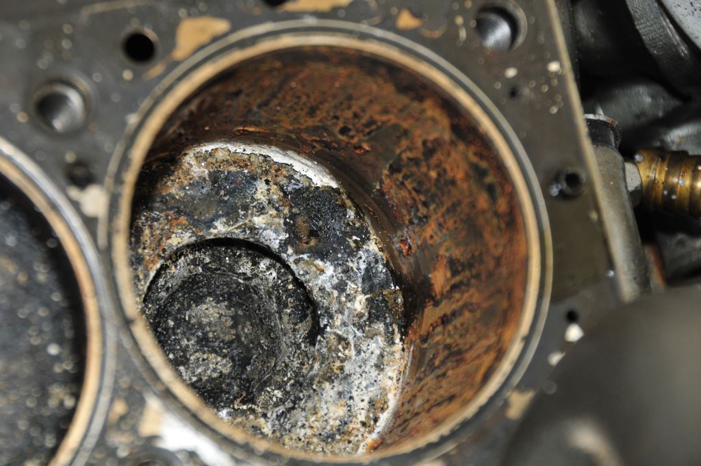
It doesn’t take long for corrosion to set in once water enters a combustion chamber.
Many propulsion engines (and gensets) installed in power vessels, and most installed in sailing vessels, are located at, or below, the waterline, making them ripe for seawater flooding. This typically occurs for one of three reasons.
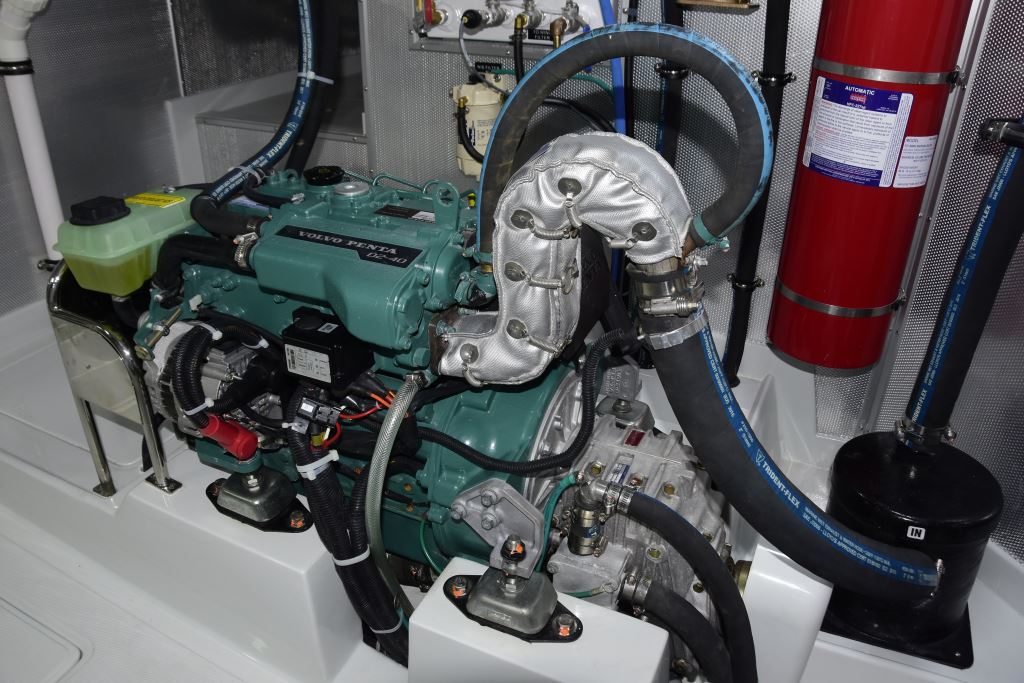
Engines, and gensets, that are located below the waterline, which is both common and normal, where water must be pushed uphill to exit the vessel, are at greater risk of flooding.
First, the engine is not installed in accordance with the manufacturer’s instructions, which are specifically designed to prevent such flooding. Violation of these rules either allows a siphon to develop, which fills the exhaust and then floods the engine’s cylinders, or water is pushed in through the exhaust discharge in a following sea, when the engine is idle, and from there through open exhaust valves and into the cylinders. Two, an anti-siphon valve malfunctions.
Defective, clogged, improperly installed, or absent anti-siphon valves can lead to engine flooding.
Three, the engine is cranked excessively while bleeding the fuel system; with each revolution a small amount of seawater is pumped by the raw water pump into the exhaust system, which eventually overflows back into the engine, and once again through an open exhaust valve and into a cylinder.
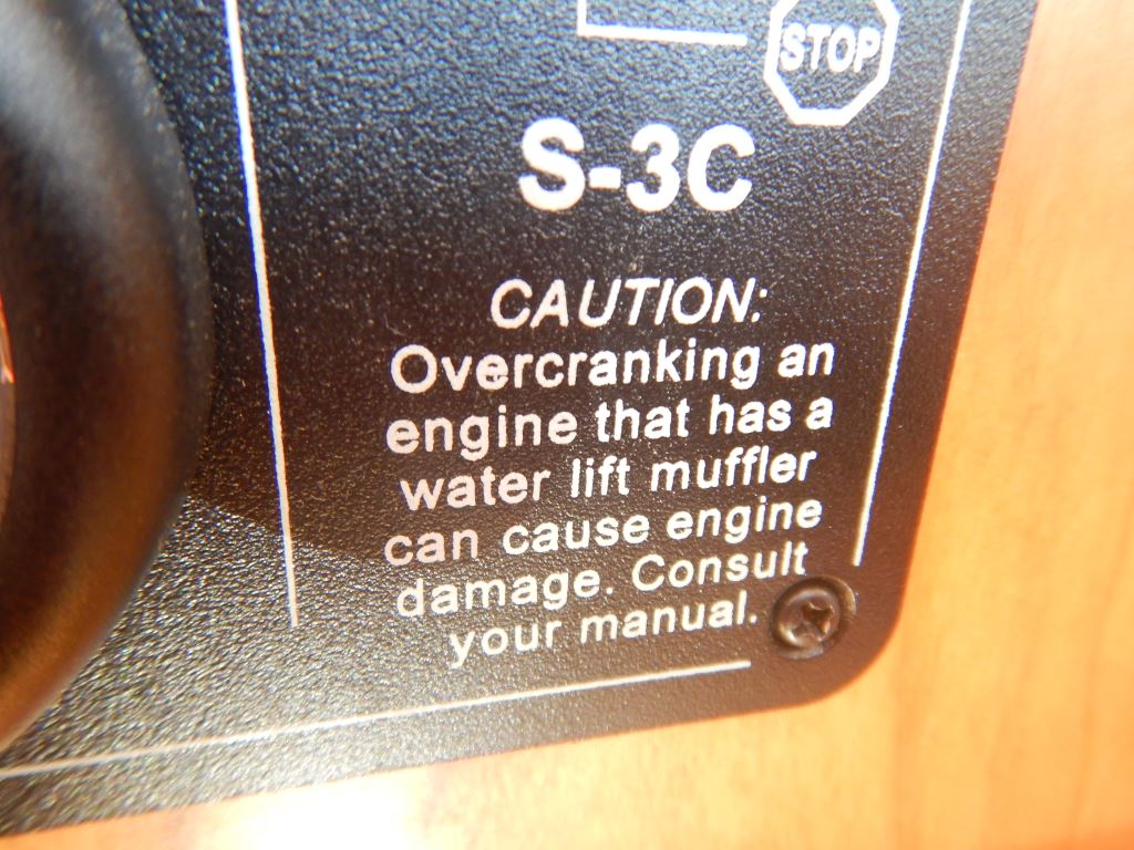
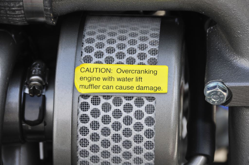
If an engine or genset is cranked excessively, a potentially normal occurrence when bleeding air from a fuel system, even a properly designed exhaust system can experience engine flooding.
I’ve covered exhaust and engine raw water system design in previous columns, those are available here, here, and here; for this column I’ll concentrate on what to do should your engine flood with seawater. Suffice it to say, remedying the symptom, i.e., water in the cylinders and crankcase, without identifying and resolving the cause, makes little sense. While no time should be wasted in removing water from the engine, do not operate it until you have identified the ingress source, and taken steps to implement corrections.
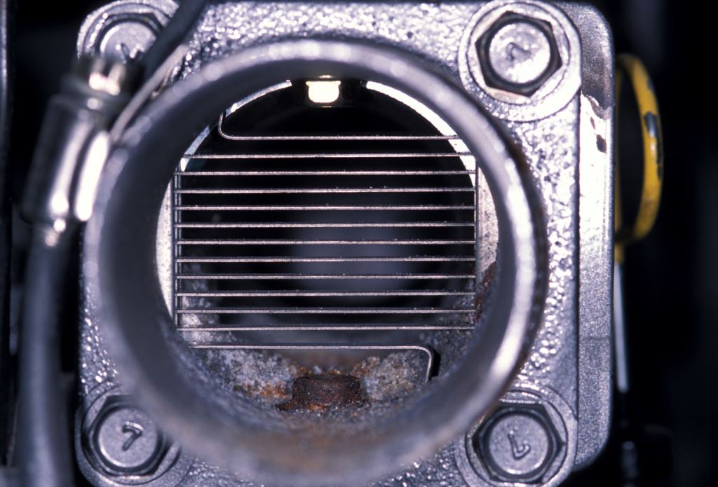
The telltale corrosion and salt accumulation at the bottom of this intake plenum is an indication this engine has experienced a flooding event.
In many cases, where I identify a manufacturer’s non-compliant exhaust system design, the response from the builder or current owner often goes something like this, “We’ve been building it that way”, or, “It’s been that way” “…for years, and it’s never been a problem”. The passage of time, or number of examples, is far from a guarantee against failure; non-compliant is non-compliant.
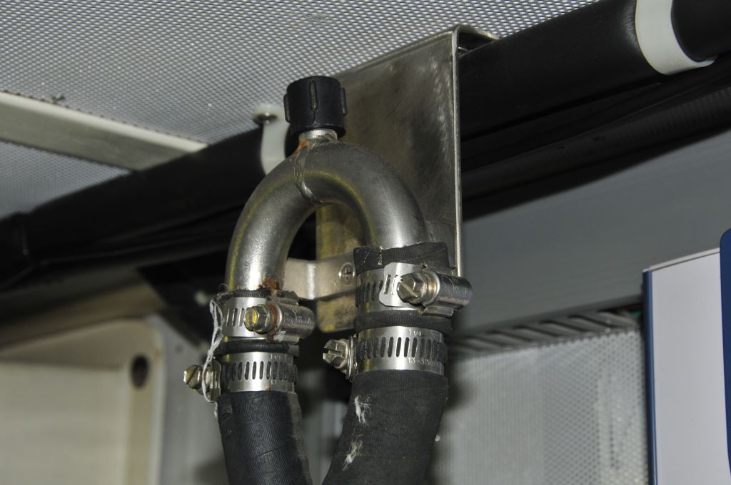
An improperly designed exhaust system, this one will trap water between the mixing elbow and muffler, is one of the leading causes of engine flooding.
This attitude is known as “normalization of deviance” it is well-documented by Diane Vaughan, in her book detailing the space shuttle Challenger explosion, “The Challenger Launch Decision” (University of Chicago, 1996). “To simply explain this complex topic: Seal problems had occurred in testing and on past shuttle flights before Challenger. But because engineers and managers saw seal issues occur with no major incident resulting, the “deviance” from the shuttle’s design — the fact that these problems were not supposed to happen — was “normalized,” meaning the flaws became more accepted.” This phenomenon, is in my experience, and unfortunately, alive and thriving in the marine industry.

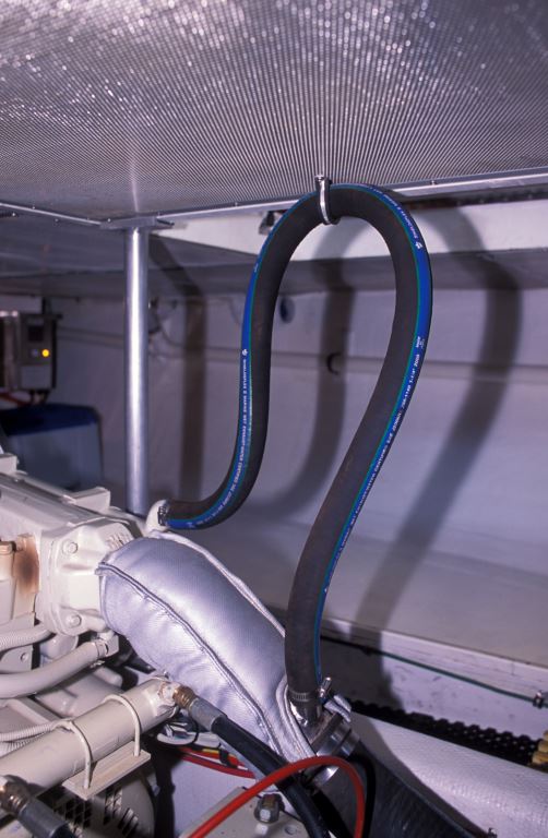
It is possible, especially for sailing vessels, for water to enter the discharge, even in a properly designed exhaust system.
It is, therefore, possible for an incipient flaw, one which leads to engine flooding, to exist for years before encountering the right conditions under which it may manifest itself; I have encountered cases where a years’ old, original equipment exhaust system, one whose design was flawed from commissioning, wherein the flooding event only occurred when the engine was switched off, and the vessel pitched bow down enough, at the same moment. Hundreds, if not thousands, of engine shut downs had occurred prior to that fateful event, except the pitch wasn’t the right degree, or at the right time, to allow water to sluice upward, and into the exhaust manifold.
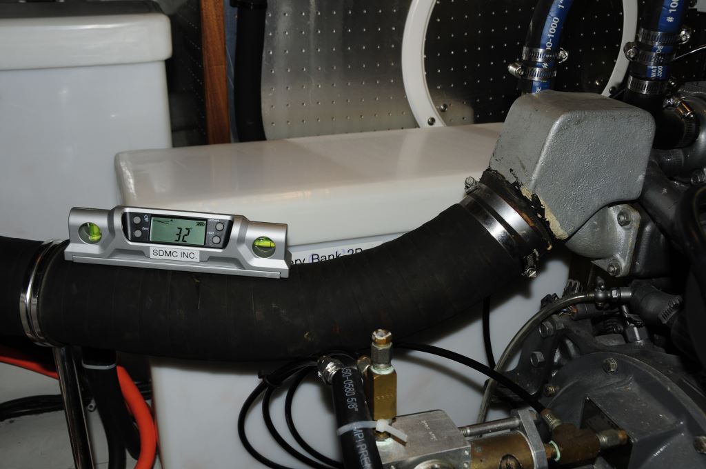
A cardinal sin of exhaust system installation involves trapping water between the mixing elbow and muffler.
It should be noted, for an engine equipped with a turbocharger and aftercooler, the latter may also fill with seawater; in which case it would need to be drained of water, flushed, and cleaned.
If the flooding has occurred within 24 hours, follow these steps.
1. Open or turn off the start battery switch, and turn off the fuel supply.
2. Wear safety glasses (I wear safety glasses whenever doing any mechanical work)
3. Remove the injectors or, if equipped with glow plugs remove those.
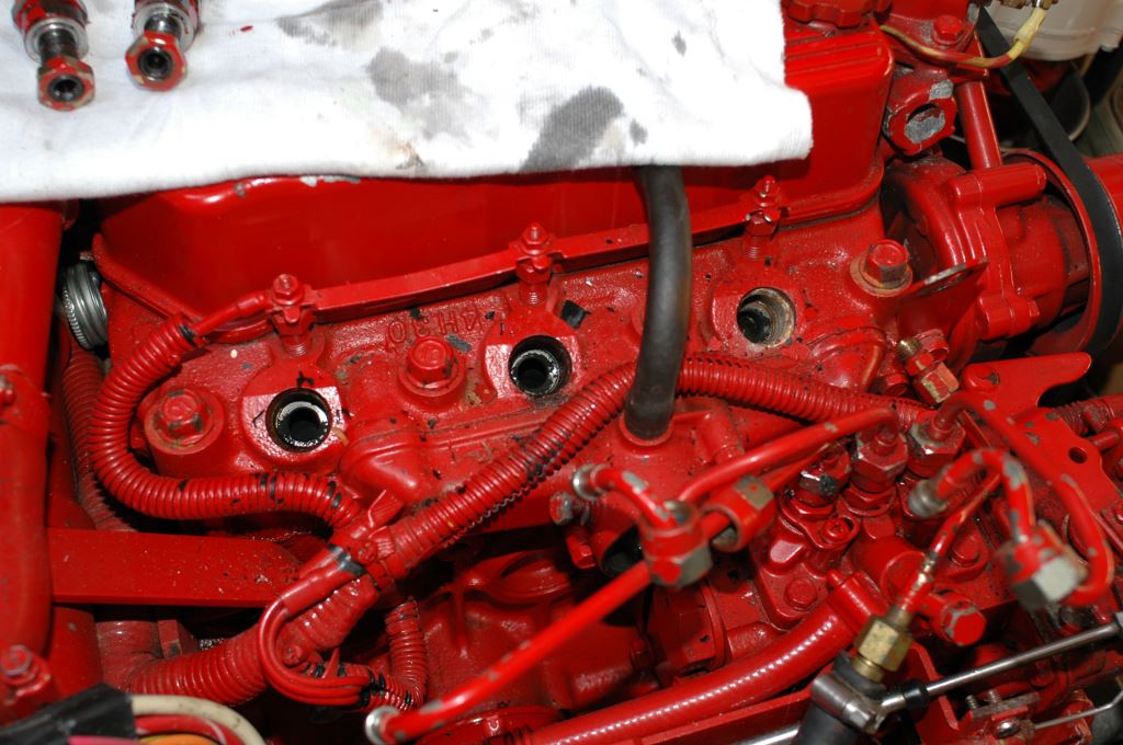
In order to allow water to exit the cylinders, injectors or glow plugs (the latter are usually easier) must be removed before attempting to manually turn over the engine.
4. Cover the exposed holes with rags and remain clear of them.
5. Turn over the engine manually, often called “barring”, by engaging a socket wrench with the alternator pulley (you may need to press down on the “slack” side of the belt to keep it from slipping). Slowly make at least two full revolutions. If you feel any resistance, stop, a valve or valves may be seized.
6. If the engine turns freely using this method, you can then crank the engine using the starter for 5-10 seconds.
7. Re-install the injectors or glow plugs.
8. Drain the oil, replace it and the filter.
9. Remove the valve cover oil fill cap (this will allow water vapor to escape more easily. Start the engine and allow it to run for about five minutes.
10. Drain and replace the oil and filter again. The oil may be milky in appearance, that is to be expected if water leaked past the piston rings and into the crankcase.
11. Start the engine and let it idle with no load for five minutes.
12. After two no load runs and oil changes, carry out an additional oil change, and run the engine under moderate load, now with the valve cover cap in place, ideally achieving an oil (not coolant) temperature of 200 degrees Fahrenheit (93 degrees centigrade), or as close to that as possible.
13. Carry out one final oil change, at this point the oil should not have a milky appearance, and run the engine normally thereafter, check the oil frequently for any signs of moisture.
If the engine has been flooded with water for more than 24 hours, it’s possible corrosion has already begun to set in within the cylinders. In that case, follow these steps.
1. Repeat steps 1-4 from above.
2. Remove the valve cover and inspect for visible damage to the valve train.
3. Pour a generous quantity of kerosene, light motor oil or automatic transmission fluid over the valve train.
4. Using a light plastic head hammer, tap each rocker arm over the valve, and observe whether the valves and rocker arms move freely, or are they seized? If any rocker arms or valves seem sticky, or don’t move immediately when tapped, there is a possibility of valve, valve train and piston damage if the starter is engaged. At this point, a decision must be made whether to remove the cylinder head.
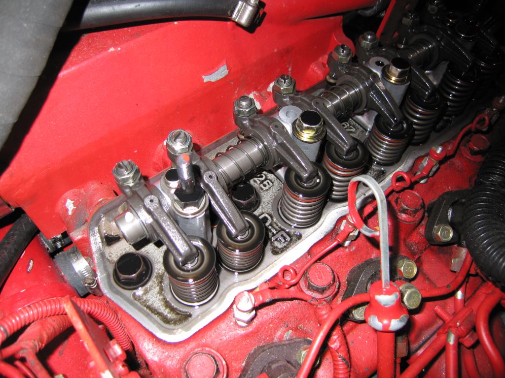
If an engine’s valve train components do not move freely, they can be damaged when the engine is rotated.
5. If all valves and rockers move freely, and if engine turns freely when barred over, disable the run function by holding the stop button or equivalent, to prevent the engine from starting, turn on the battery switch, and spray fogging oil into the air intake (remove the air filter if present) while cranking the engine with the starter for 30 seconds.
6. Continue from step 8 above.
If this scenario is caught early, in most cases it can be resolved with no permanent damage.

