
Photo Essay: Through Deck Fittings
Properly securing deck hardware can present a variety of challenges. Cored composite decks represent perhaps the greatest challenge; the core material must either be excluded during the deck lay-up phase of vessel construction, or it must be removed and back-filled with thickened epoxy (you can read more about that process here).
For most vessels deck hardware is heavily loaded, a critical component, or both; this includes everything from cleats and windlasses to stanchions and life raft cradles, all of which must be securely fastened to, or through, the deck, and yet in too many examples I encounter flaws in these installations in the form of absent, or undersized backing plates, or backing plates that are made of the wrong material, the most common of which is UHMW, often known by its trade name “Starboard”. Backing plates should be stainless steel, aluminum, GPO3 or G10.
In the example shown here, fasteners securing a cleat exit the underside of the deck, whose surface is uneven. As a result, the load is not being supported by the fasteners, or their washers, evenly, and no backing plate is present (if the deck is heavily laminated and designed to support the load, it may be possible to forgo backing plates).
Furthermore, water is leaking through the fastener penetrations, which is leading to crevice corrosion (more on that subject here), which in turn could lead to failure of these fasteners when heavily stressed.
The proper approach for a scenario of this sort is to install a backing plate whose surface is perpendicular with the fasteners. This can be established by “mushing” it in place using thickened epoxy.
Ask Steve
Steve,
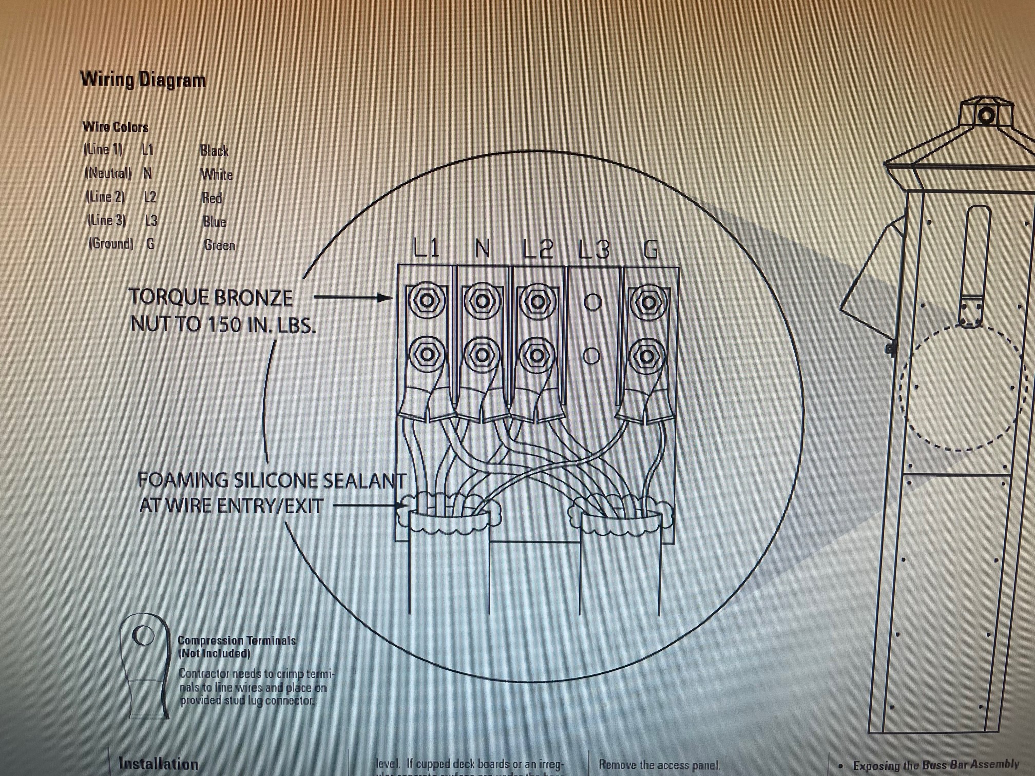
I’ve been told that it’s proper to bond the neutral and ground together at the shore power pedestal. This goes against everything I know about electrical wiring. Here’s a diagram from Eaton that shows them isolated. What’s up?
Thank you!
Michael Pearson
Michael:
Aboard a vessel, ABYC Standards dictate that the neutral and ground are to be bonded at sources of power, when, and only when, they are the sources of power. Inverters and generators as well as shore power transformers are considered sources of power aboard. With one exception, the neutral to ground bond must be present only when the inverter or generator is producing power, otherwise there must be no other neutral to ground bonds aboard. The neutral and ground may be permanently bonded aboard, either at the transformer or at the main panel, only if the vessel is equipped with a shore power transformer.
As for the pedestal, which falls outside the preview of ABYC, it is not considered a source of power, and thus the neutral and ground should not be bonded there. The neutral and ground are typically bonded ashore at the transformer (which, once again, is considered a source of power) that supplies the marina or dock. Thus, the diagram is correct.
More on neutral to ground bonding here.
It is strongly recommended that electrical work, especially that related to shore power, be carried out by a trained and certified electrician.
Hi Steve:
I love your articles; I get a lot out of every one of them. Thanks for sharing your knowledge.
Your article on lightning was great. (That statistic about catamarans blows me away – what’s with that?!) My question is about lightning and grounding on metal, or in my specific case, aluminum sailboats. I’ve often heard it said that you have less to be concerned with on an aluminum boat. All my thru-hulls are Marelon, all my transducers are plastic. And, the key to antifouling is to have a perfect epoxy barrier coat, which would seem to negate the ability of a hull to ground to the water. My electrical system and engine ground is ‘floating’. Although my boat has a couple of welded-on aluminum all-thread that the hull zincs spin on to. Given your “1 square foot” guidance for a grounding plate, it doesn’t seem like my zincs meet the standard. I’d guess that somewhere in my skeg-hung rudder system, there may be bare metal in contact with water that could act as a partial ground too.
Anyway, I’m wondering if you have experience with aluminum boats having lightning strikes and issues you may have seen, and what, if anything, I should do or be aware of. And should there be a ground plate of some sort and of what material?
Many thanks,
Peter Haeussler
Peter:
It is true, an alloy vessel is a Faraday cage of sorts, which means it offers better protection to those aboard in the event of a strike, when compared to fiberglass or timber vessels. They require little or nothing in the way of lightning-strike mitigation wiring. The epoxy barrier coat, while excluding moisture, is so thin that it effectively acts like a capacitor; it won’t inhibit the grounding effect. This is no different than an external lead or iron ballast keel that is similarly barrier coated, and is used for grounding purposes.
From a lightning strike dissipation, corrosion protection and AC electrocution prevention, I don’t fully agree with the floating ground approach. At the very least, all AC power supplies must be ELCI and GFCI protected to guard against electrocution or electric shock drowning associated with a fault to the hull. An ABYC committee is working on an isolated ground standard, to clarify some of the issues associated with these systems for builders, repairers and owners.
These articles provide additional details…
- Electric Shock Drowning
- Electrocution Prevention
- Shore Power Transformers
- Aluminum Corrosion
- More on lightning
As far as the increased frequency of catamaran lightning strikes, lightning expert Dr. Ewen Thomson explains it on his website page.
Hi Steve,
We have a 1984 Hatteras 53 extended deckhouse motor yacht with the standard 32-volt electrical system. We lack an inverter and house battery bank system.
Would you have any guidance for installing a system that will run the refrigerator, the occasional microwave or coffee pot, and some electrical outlets?
Likely, there are some others who have similar Hatteras vessels.
Thanks for any guidance!
David Randall
David:
With a 32-volt system you will be challenged, I know if no common inverters that run on this voltage.
Short of converting the entire vessel to 24-volts, which is no small task, the only practical solution is to create a 24-volt bank for an inverter/charger. It will need a charge source in the form of an alternator. Vessels with dual DC voltages are not uncommon, so this is doable and it would not be that unusual. You could also incorporate a 32-to-24-volt DC-DC converter so you can take advantage of the existing charge sources for the 32-volt system.

