
Photo Essay: Plumbing Bonding Technique
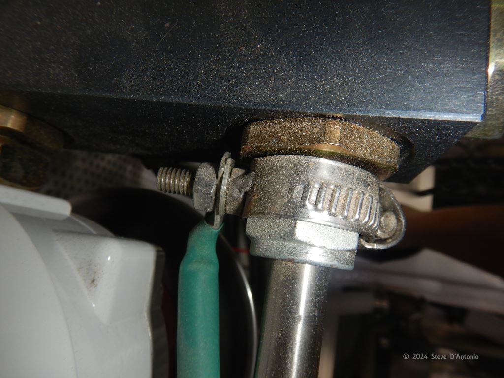
As I carry out inspections, one of the issues I frequently encounter involves bonding or grounding (there is a difference, but we’ll leave that for another column) of metallic fuel, water, and hydraulic plumbing components. Some of these components have built in fasteners that are designed to accept a ring terminal, including and especially seacocks. Many, however, have no fastener or provisions for attachment of wires, and so boat builders and technicians are left to devise a means of reliably making a low resistance (for cathodic or corrosion protection, the maximum allowable resistance between an anode and a protected metal is one ohm) connection to these items. In too many cases this means a section of bare wire attached to a plumbing fitting with a hose clamp. These are prone to corrosion, loosening, and damage to wire strands. An only slightly better scenario involves a ring or barrel terminal retained under a hose clamp.
The accompanying image depicts what I believe is the best approach I’ve encountered yet; a stud that is passed through a hole that has been drilled in a hose clamp. The clamp presses the head of the screw tightly against the plumbing fitting, making good, reliable, and low resistance contact, and a ring terminal is then placed over what is now a stud. In this case the installer has also gone the extra step of welding the fastener to the hose clamp. While that represents a belt and suspenders approach, I don’t believe it is necessary to achieve the required low resistance connection with the the bonding or grounding systems.
Ask Steve
Hello Steve,
I read your 2022 article on grounding… very informative.
I must install a ground for my vessel, it is a catamaran so the mast is placed amidships on the bridge deck, 5 ft. above the water. The vessel is composite, a Lagoon 500.
I have to comply with Transport Canada’s electrical standard which follows…
- LIGHTNING CONDUCTORS
23.1 Lightning conductors shall be fitted to each mast of all wooden and composite ships and to each mast of steel or aluminum ships having wooden masts or topmasts except where the height of any antenna exceeds that of the masts and the antenna is equipped with lightning arresters or other effective devices.
23.2 Lightning conductors shall be made of continuous copper alloy tape or cable having a cross-sectional area not less than 25 mm² (#4 AWG) which shall be riveted with copper rivets or fastened with copper clamps to a suitable copper spike (air terminal) not less than 13 millimetres in diameter, projecting at least 150 millimetres above the top of the mast.
23.3 Where copper tape is used, its lower end shall terminate at the point at which the shrouds leave the mast and shall be securely clamped to a copper conductor not less than 13 millimetres in diameter
23.4 The copper conductor shall be led down the shrouds and shall be securely clamped to a copper plate not less than 0.2 m² in area, fixed well below the light-load waterline and attached to the ship’s side in such a manner that it is immersed under all conditions of heel and trim.
23.5 In wooden and composite ships fitted with steel masts, each mast shall be connected to a copper plate in accordance with subsection (4) and the copper rope or tape being securely attached to and in good electrical contact with the mast at or above the point at which the shrouds leave the mast.
23.6 Lightning conductors shall be run as straight as possible and sharp bends in the conductors shall be avoided; all clamps shall be of brass or copper, preferably of the serrated contact type, and shall be effectively locked.
23.7 The resistance of the lightning conductor, measured between the mast head and the position on the ground plate or hull to which the lightning conductor is grounded, shall not exceed 0.02 ohm.
23.8 Vessels in which tank vent outlets for flammable gases is located near, or at the top of a non-conductive mast are to be protected by and air terminal at least 2 metres above the vent outlet; on a steel mast the steel mast must extend at least 2 metres above the vent outlet.
My question to you is, what is the best way to get to the ground while minimizing any horizontal runs in the main conductor? Will I need to run the #4 cale form the masthead down to the first shroud, down that shroud to the chain plates and then transfer it to an interior #4 cable and inside the hull to the attachment point of the stud on the grounding plate? Or is the shroud, which is quite substantial, suitable as the #4 ground wire, where I could then just make the connection from the mast head down to the shroud, and then from the chain plates to the grounding plates with #4 wire. Is one side sufficient, or do both hulls need to be done?
According to your article the best grounding plate should be, (to be .2m^2. per TC) longer and narrower perhaps 2mX0.1m for most efficacy, at5 or 6 mm thick.
Currently the vessel has two grounds per side as manufactured, plus a larger one on the starboard side. They are only connected to the chainplates on either side of the catamaran.
Can these be used in the system?
Your comments and advice would be greatly appreciated.
Regards,
Captain Gregory Heroux
Greg:
Catamarans are significantly more prone to lightning strikes than mono-hulls, so your efforts to install a lightning strike mitigation system are to be applauded.
Complying with Transport Canada’s electrical standard is a tall order to say the least. As it mentions “ships”, I wonder, does it apply to your small, recreational craft? I have reviewed many Canadian yachts, and have never encountered one that complied with this guideline, in the manner described.
No mention is made of aluminum alloy spars, which are the most common, which once again makes me wonder if it applies to recreational small craft, however, it sounds as if, to comply, you must attach a 4/0 conductor to the mast, at the shroud (rather than at the masthead), and then lead that conductor down the shroud(s), through the deck, and thence to a ground plate. I’ve worked in the marine industry since 1988, and once again I’ve never seen such an arrangement.
Based on the standard, it does not sound as if you can use a shroud as a down conductor. You might gain an exemption if, using the shrouds as down conductors, you were able to meet the (lofty) maximum allowable resistance of 0.02 ohms, which is tantamount to zero resistance, making it very unlikely. I would argue the resistance in the lengthy test leads needed to perform such a test, would exceed the threshold.
Aluminum spars are excellent conductors, and are frequently used as “down conductors”, and on the vast majority of sailing vessels they are used for just that purpose, whether by design or default, however, that’s problematic for a catamaran as the mast foot is not below the waterline or even close to the water, relatively speaking, and when compared to a mono-hull. While sharp bends in down conductors should be avoided, doing so is often difficult, again especially on catamarans.
Using the shrouds as down conductors (or connecting a 4/0 cable to the spar where the shrouds are attached), and then using 4/0 cable to connect the chain plates to ground plates, would be the most practical and common approach if you intend to (mostly) comply with this standard. Attaching a 4/0 cable to the base of the spar and then to a ground plate as well, wouldn’t hurt, even if it does involve a 90-degree turn. While larger is better where lightning is concerned, it should be noted that the 4/0 cable size requirement significantly exceeds the ABYC Lightning Standard TE-4, which is detailed in the article you read, and which is linked below, as do other elements of the Transport Canada guidelines.
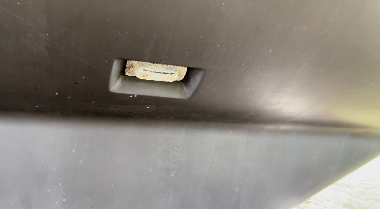
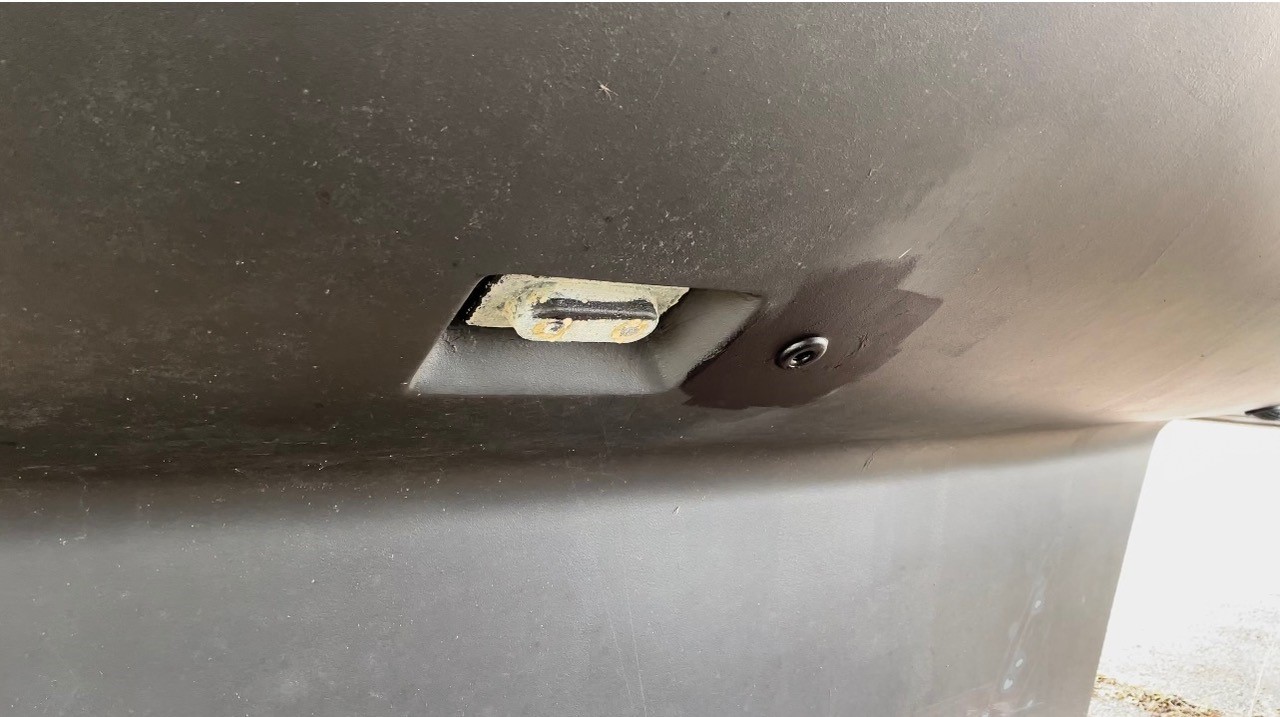
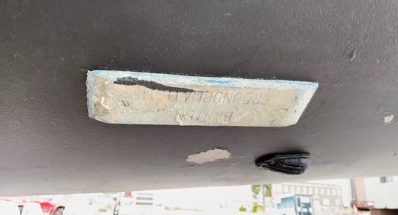
The photos you shared of ground plates, at least one depicts a common product made form sintered bronze. The others appear to be anodes. Strictly speaking, these do not meet the requirements for a solid copper plate, with sharp edges, detailed in the article.
There are no guarantees where lightning is concerned, and the best, practical efforts should be made to provide some means of safely conveying lightning current from a mast to the water.
Further reading…
- https://stevedmarineconsulting.com/lightning-toeing-the-standards-line-editorial-knowing-when-to-self-regulate/
- https://stevedmarineconsulting.com/wp-content/uploads/2021/11/Lightning193-FINAL.pdf
- https://stevedmarineconsulting.com/wp-content/uploads/2022/02/TaskSheetGround-Ground-Plate-195-02.pdf
Steve,
I’d wager you receive an awful lot of email with questions about various boat issues. I have two issues that came up recently that might be of interest to you and your readers. I don’t recall seeing either of these issues in your past posts. A cursory search of your posts did not turn up a match.
Invictus is my 32′ Nordic Tug, 1997 vintage, with approx. 3000 hours on a Cummins 6BT5.9M.
The first issue is in regard to my 5″ water-cooled main engine exhaust hose between the engine and fiberglass elbow leading to the muffler. I noted small rust spots on the outer jacket last fall. The spots got bigger during this summer’s cruising. This was a clear ‘heads up’ that something was amiss so I decided to replace the hose. I was surprised when I removed the old hose to see that most of the inside lining of the hose had delaminated and big flaps were seriously impeding the flow of exhaust and cooling water (see photos). A new hose is now installed. My questions involve a confession first. I have had two instances when I started the engine and got underway without opening the raw water intake valve. No excuses. Just plain forgot. In both instances I caught it quickly because the PSS shaft seal started squealing (no lubricating water). Could it have been those short periods without water that caused the damage to my exhaust hose or should I be looking for some other cause? Or was the hose simply worn out? Could the restricted exhaust and water flow explain the gradual increase I have noted in engine temperature while underway? Usual engine operating temperature over the past 13 years has been 183° at 1650 rpm. Recently, over a period of hours the temperature will gradually climb from 183° up to 188°, higher if I increase rpm. I have checked numerous other possible causes of this increase without finding the culprit.
The second issue is in regard to the ball joint rod end connector between hydraulic cylinder and rudder tiller arm. While underway on autopilot this summer with the Admiral driving, I went into the lazarette and noticed that there was movement between the rudder tiller and the ball joint rod end. A visual inspection of the portion that I could see did not find anything alarming. I guessed the likely reason was wear and tear on the 5/8″ bolt that connects the rod end to the tiller and decided to replace it at season’s end. When I dismantled the joint, I was surprised to see that the connector was broken clean through around the ball. I have had this boat since 2010 and have never hit anything with the rudder, at least that I am aware of. And surely if I hit something hard enough to break the rod end, I would be aware of it. So, I wonder if it was something other than an impact that broke the rod end? You can see from the [not very good] photo that there is rust on the face of the break. Since this fitting is stainless steel, I wonder if there may have been a crack there from the manufacturer and crevice corrosion did its thing? Or is there a weld there that hardened and eventually failed? Can you speculate on what caused this crack? Maybe this joint is something for all of us to check periodically while underway? Should I replace it with a similar rod end or should I switch to a clevis style connector?
I really enjoy your periodic posts. Please keep it up!
Peter Shaughnessy
Peter:
Coincidentally, I recently encountered a similar delaminated exhaust hose on a generator application. There are four things that can account for this. First, a hose that is not rated for exhaust use. Hoses used in wet exhaust applications should carry a “SAE J2006” designation (this needs to be printed on the hose, if the hose is devoid of any markings, it is unsuitable). Second, use of low quality, budget or off-brand hose. Third, an overheat. If the engine runs without water, even briefly, the exhaust system will be subject to dry exhaust gasses, which can range from 400-1000 degrees Fahrenheit (204-538 degrees centigrade), enough to damage and breach the hose’s inner liner. Once that occurs, the water will be forced between the liner and next layer, leading to delamination. Fourth, an exhaust system whose down angle at the point of water injection is too shallow. This arrangement causes water starvation at the top of the inside of the hose, which leads to localized overheating of the hose, which in turn cause to delaminate. Cummins requires a minimum exhaust angle of 15 degrees. More on exhaust system angles and design here.
The delamination will almost certainly increase back-pressure in the exhaust system (more on that subject here), which can lead to increased fuel consumption and higher jacket water operating temperatures. My strong recommendation would be to add, if not already present, a wet exhaust temperature alarm (this is a requirement for ABYC compliance). More on these here. This alarm will alert you to a restriction or loss of water flow to the exhaust system almost immediately, typically long before any damage to the hose (or engine for that matter) can occur.
The steering ram end fitting, sometimes called a ball joint rod end, failure is note-worthy for two reasons. First, unless it was removed, I don’t see the plastic insert that is often present between the inner ball and the outer cage. If it’s missing, there would be considerable slop in the system. The plastic insert is slippery, providing lubrication, which means no grease is required. If none was present from the start, the ball joint would usually be equipped with bronze bushing and a zerk fitting, to allow the injection of grease, or a small hole, which also is used to inject grease with a rubber tip grease gun fitting (those are not common, so these often go ungreased, see the example photo below).
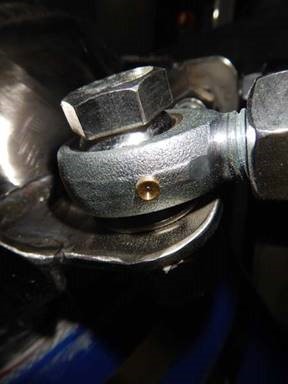
Two, the cage appears to have “sprung”, which seems odd, as if it was under tension, or it elongated after the crack occurred. Either way, this is a disconcerting failure. The rust is indicative of crevice corrosion, all that’s needed for that to begin is a micro-fracture and seawater. Was it getting wet? Also, in this design, the fasteners that secures the ball joint to the tiller arm should never wear out; if it is properly tensioned, it becomes one with the center ball, within the cage, so all the movement, and wear, occurs between the inner ball and the cage (or the insert or bushing). If the fastener is allowed to move, it will wear, and this will also cause wear inside the hole through which it passes in the tiller arm. This detail is often lost even on boat builders, who believe the fastener must be left loose to prevent binding.
When replacing the ball joint end, make certain the locking nut is good and tight to prevent the ram rod from spinning and unscrewing from the ball joint, which would cause a loss of steering; I recommend the use of a thread locking compound here and TorqueSeal. If it is the greaseable variety, make certain it is greased with a good, heavy chassis grease, and if water is leaking into this area, get that resolved. More on hydraulic steering system design, installation and maintenance here.
Steve,
I have been slowly working through documenting all of our processes and procedures which have been “tribal knowledge” for decades in an effort to provide good teaching material for our apprenticeship program. One thing that has consistently stumped me is finding anything more than a broad comment on torque for propeller nuts. Rarely is anything more than “ensure that the nut is properly torqued” or “torque so that the prop hub is seated” or “just enough” used in any publication, including ABYC! Clearly this is an area that is ripe for issue when my “firm” is the next guy’s “reefed on” or vise-a-versa. Do you have a reference for torque on propeller nuts and does that account for varying shaft sizes?
Thanks for your time Steve. I always appreciate your newsletter and articles. They provide inspiration and answers for a lot of us in the industry.
With Kind Regards,
Ben Van Dam
Ben:
I’ve been asked this question on many occasions, and for most of my career, I had no answer than, “tight enough”. A few years ago, however, I decided to dig into this and was finally provided with an answer from Peter Stolper, from Seatorque, manufacturer of the “Bolt On Shaft System”, a prop shaft and thrust bearing system. To the best of my knowledge this is accurate, however, I suspect most folks will continue to tighten prop nuts until they are…tight enough.
Here is his formula…
Firstly, on a propeller taper, the propeller hub has to be pressed onto the taper using more force than the thrust generated by the propeller itself.
This ensures that it will not move further up the taper under normal thrust loads thereby loosening the propeller nut.
(using 3” diameter shaft as illustration)
In tons, the clamping force required is:
Nominal diameter of shaft x condition factor.
(Factor 2.875 is dry taper; 2.6 is for oiled taper)
3 x 2.875 = 8.625 TonsF.
Convert to Lbs.:
8.625 x 2240 Lbs. = 19,320 LbsF.
Torque required on nut to deliver clamping force of 19,320 Lbs:
(Nom Diameter of thread (2.25) x Factor x LbsF) / 12).
(Factor is 0.2 for dry thread; 0.15 for oiled thread)
2.25 x 0.2 x 19,320 = 8,694 Inch/Lbs.
Divided by 12 = 724 Ft/Lbs.

